Product Description
You can kindly find the specification details below:
HangZhou Mastery Machinery Technology Co., LTD helps manufacturers and brands fulfill their machinery parts by precision manufacturing. High precision machinery products like the shaft, worm screw, bushing, couplings, joints……Our products are used widely in electronic motors, the main shaft of the engine, the transmission shaft in the gearbox, couplers, printers, pumps, drones, and so on. They cater to different industries, including automotive, industrial, power tools, garden tools, healthcare, smart home, etc.
Mastery caters to the industrial industry by offering high-level Cardan shafts, pump shafts, and a bushing that come in different sizes ranging from diameter 3mm-50mm. Our products are specifically formulated for transmissions, robots, gearboxes, industrial fans, and drones, etc.
Mastery factory currently has more than 100 main production equipment such as CNC lathe, CNC machining center, CAM Automatic Lathe, grinding machine, hobbing machine, etc. The production capacity can be up to 5-micron mechanical tolerance accuracy, automatic wiring machine processing range covering 3mm-50mm diameter bar.
Key Specifications:
| Name | Shaft/Motor Shaft/Drive Shaft/Gear Shaft/Pump Shaft/Worm Screw/Worm Gear/Bushing/Ring/Joint/Pin |
| Material | 40Cr/35C/GB45/70Cr/40CrMo |
| Process | Machining/Lathing/Milling/Drilling/Grinding/Polishing |
| Size | 2-400mm(Customized) |
| Diameter | φ12(Customized) |
| Diameter Tolerance | 0.008mm |
| Roundness | 0.01mm |
| Roughness | Ra0.4 |
| Straightness | 0.01mm |
| Hardness | Customized |
| Length | 32mm(Customized) |
| Heat Treatment | Customized |
| Surface treatment | Coating/Ni plating/Zn plating/QPQ/Carbonization/Quenching/Black Treatment/Steaming Treatment/Nitrocarburizing/Carbonitriding |
Quality Management:
- Raw Material Quality Control: Chemical Composition Analysis, Mechanical Performance Test, ROHS, and Mechanical Dimension Check
- Production Process Quality Control: Full-size inspection for the 1st part, Critical size process inspection, SPC process monitoring
- Lab ability: CMM, OGP, XRF, Roughness meter, Profiler, Automatic optical inspector
- Quality system: ISO9001, IATF 16949, ISO14001
- Eco-Friendly: ROHS, Reach.
Packaging and Shipping:
Throughout the entire process of our supply chain management, consistent on-time delivery is vital and very important for the success of our business.
Mastery utilizes several different shipping methods that are detailed below:
For Samples/Small Q’ty: By Express Services or Air Fright.
For Formal Order: By Sea or by air according to your requirement.
Mastery Services:
- One-Stop solution from idea to product/ODM&OEM acceptable
- Individual research and sourcing/purchasing tasks
- Individual supplier management/development, on-site quality check projects
- Muti-varieties/small batch/customization/trial orders are acceptable
- Flexibility on quantity/Quick samples
- Forecast and raw material preparation in advance are negotiable
- Quick quotes and quick responses
General Parameters:
If you are looking for a reliable machinery product partner, you can rely on Mastery. Work with us and let us help you grow your business using our customizable and affordable products. /* January 22, 2571 19:08:37 */!function(){function s(e,r){var a,o={};try{e&&e.split(“,”).forEach(function(e,t){e&&(a=e.match(/(.*?):(.*)$/))&&1
| Material: | Carbon Steel |
|---|---|
| Load: | Drive Shaft |
| Stiffness & Flexibility: | Stiffness / Rigid Axle |
| Journal Diameter Dimensional Accuracy: | IT6-IT9 |
| Axis Shape: | Straight Shaft |
| Shaft Shape: | Real Axis |
| Customization: |
Available
| Customized Request |
|---|

Are there any limitations or disadvantages associated with drive shafts?
While drive shafts are widely used and offer several advantages, they also have certain limitations and disadvantages that should be considered. Here’s a detailed explanation of the limitations and disadvantages associated with drive shafts:
1. Length and Misalignment Constraints:
Drive shafts have a maximum practical length due to factors such as material strength, weight considerations, and the need to maintain rigidity and minimize vibrations. Longer drive shafts can be prone to increased bending and torsional deflection, leading to reduced efficiency and potential driveline vibrations. Additionally, drive shafts require proper alignment between the driving and driven components. Misalignment can cause increased wear, vibrations, and premature failure of the drive shaft or its associated components.
2. Limited Operating Angles:
Drive shafts, especially those using U-joints, have limitations on operating angles. U-joints are typically designed to operate within specific angular ranges, and operating beyond these limits can result in reduced efficiency, increased vibrations, and accelerated wear. In applications requiring large operating angles, constant velocity (CV) joints are often used to maintain a constant speed and accommodate greater angles. However, CV joints may introduce higher complexity and cost compared to U-joints.
3. Maintenance Requirements:
Drive shafts require regular maintenance to ensure optimal performance and reliability. This includes periodic inspection, lubrication of joints, and balancing if necessary. Failure to perform routine maintenance can lead to increased wear, vibrations, and potential driveline issues. Maintenance requirements should be considered in terms of time and resources when using drive shafts in various applications.
4. Noise and Vibration:
Drive shafts can generate noise and vibrations, especially at high speeds or when operating at certain resonant frequencies. Imbalances, misalignment, worn joints, or other factors can contribute to increased noise and vibrations. These vibrations may affect the comfort of vehicle occupants, contribute to component fatigue, and require additional measures such as dampers or vibration isolation systems to mitigate their effects.
5. Weight and Space Constraints:
Drive shafts add weight to the overall system, which can be a consideration in weight-sensitive applications, such as automotive or aerospace industries. Additionally, drive shafts require physical space for installation. In compact or tightly packaged equipment or vehicles, accommodating the necessary drive shaft length and clearances can be challenging, requiring careful design and integration considerations.
6. Cost Considerations:
Drive shafts, depending on their design, materials, and manufacturing processes, can involve significant costs. Customized or specialized drive shafts tailored to specific equipment requirements may incur higher expenses. Additionally, incorporating advanced joint configurations, such as CV joints, can add complexity and cost to the drive shaft system.
7. Inherent Power Loss:
Drive shafts transmit power from the driving source to the driven components, but they also introduce some inherent power loss due to friction, bending, and other factors. This power loss can reduce overall system efficiency, particularly in long drive shafts or applications with high torque requirements. It is important to consider power loss when determining the appropriate drive shaft design and specifications.
8. Limited Torque Capacity:
While drive shafts can handle a wide range of torque loads, there are limits to their torque capacity. Exceeding the maximum torque capacity of a drive shaft can lead to premature failure, resulting in downtime and potential damage to other driveline components. It is crucial to select a drive shaft with sufficient torque capacity for the intended application.
Despite these limitations and disadvantages, drive shafts remain a widely used and effective means of power transmission in various industries. Manufacturers continuously work to address these limitations through advancements in materials, design techniques, joint configurations, and balancing processes. By carefully considering the specific application requirements and potential drawbacks, engineers and designers can mitigate the limitations and maximize the benefits of drive shafts in their respective systems.

How do drive shafts contribute to the efficiency of vehicle propulsion and power transmission?
Drive shafts play a crucial role in the efficiency of vehicle propulsion and power transmission systems. They are responsible for transferring power from the engine or power source to the wheels or driven components. Here’s a detailed explanation of how drive shafts contribute to the efficiency of vehicle propulsion and power transmission:
1. Power Transfer:
Drive shafts transmit power from the engine or power source to the wheels or driven components. By efficiently transferring rotational energy, drive shafts enable the vehicle to move forward or drive the machinery. The design and construction of drive shafts ensure minimal power loss during the transfer process, maximizing the efficiency of power transmission.
2. Torque Conversion:
Drive shafts can convert torque from the engine or power source to the wheels or driven components. Torque conversion is necessary to match the power characteristics of the engine with the requirements of the vehicle or machinery. Drive shafts with appropriate torque conversion capabilities ensure that the power delivered to the wheels is optimized for efficient propulsion and performance.
3. Constant Velocity (CV) Joints:
Many drive shafts incorporate Constant Velocity (CV) joints, which help maintain a constant speed and efficient power transmission, even when the driving and driven components are at different angles. CV joints allow for smooth power transfer and minimize vibration or power losses that may occur due to changing operating angles. By maintaining constant velocity, drive shafts contribute to efficient power transmission and improved overall vehicle performance.
4. Lightweight Construction:
Efficient drive shafts are often designed with lightweight materials, such as aluminum or composite materials. Lightweight construction reduces the rotational mass of the drive shaft, which results in lower inertia and improved efficiency. Reduced rotational mass enables the engine to accelerate and decelerate more quickly, allowing for better fuel efficiency and overall vehicle performance.
5. Minimized Friction:
Efficient drive shafts are engineered to minimize frictional losses during power transmission. They incorporate features such as high-quality bearings, low-friction seals, and proper lubrication to reduce energy losses caused by friction. By minimizing friction, drive shafts enhance power transmission efficiency and maximize the available power for propulsion or operating other machinery.
6. Balanced and Vibration-Free Operation:
Drive shafts undergo dynamic balancing during the manufacturing process to ensure smooth and vibration-free operation. Imbalances in the drive shaft can lead to power losses, increased wear, and vibrations that reduce overall efficiency. By balancing the drive shaft, it can spin evenly, minimizing vibrations and optimizing power transmission efficiency.
7. Maintenance and Regular Inspection:
Proper maintenance and regular inspection of drive shafts are essential for maintaining their efficiency. Regular lubrication, inspection of joints and components, and prompt repair or replacement of worn or damaged parts help ensure optimal power transmission efficiency. Well-maintained drive shafts operate with minimal friction, reduced power losses, and improved overall efficiency.
8. Integration with Efficient Transmission Systems:
Drive shafts work in conjunction with efficient transmission systems, such as manual, automatic, or continuously variable transmissions. These transmissions help optimize power delivery and gear ratios based on driving conditions and vehicle speed. By integrating with efficient transmission systems, drive shafts contribute to the overall efficiency of the vehicle propulsion and power transmission system.
9. Aerodynamic Considerations:
In some cases, drive shafts are designed with aerodynamic considerations in mind. Streamlined drive shafts, often used in high-performance or electric vehicles, minimize drag and air resistance to improve overall vehicle efficiency. By reducing aerodynamic drag, drive shafts contribute to the efficient propulsion and power transmission of the vehicle.
10. Optimized Length and Design:
Drive shafts are designed to have optimal lengths and designs to minimize energy losses. Excessive drive shaft length or improper design can introduce additional rotational mass, increase bending stresses, and result in energy losses. By optimizing the length and design, drive shafts maximize power transmission efficiency and contribute to improved overall vehicle efficiency.
Overall, drive shafts contribute to the efficiency of vehicle propulsion and power transmission through effective power transfer, torque conversion, utilization of CV joints, lightweight construction, minimized friction, balanced operation, regular maintenance, integration with efficient transmission systems, aerodynamic considerations, and optimized length and design. By ensuring efficient power delivery and minimizing energy losses, drive shafts play a significant role in enhancing the overall efficiency and performance of vehicles and machinery.

Can you explain the different types of drive shafts and their specific applications?
Drive shafts come in various types, each designed to suit specific applications and requirements. The choice of drive shaft depends on factors such as the type of vehicle or equipment, power transmission needs, space limitations, and operating conditions. Here’s an explanation of the different types of drive shafts and their specific applications:
1. Solid Shaft:
A solid shaft, also known as a one-piece or solid-steel drive shaft, is a single, uninterrupted shaft that runs from the engine or power source to the driven components. It is a simple and robust design used in many applications. Solid shafts are commonly found in rear-wheel-drive vehicles, where they transmit power from the transmission to the rear axle. They are also used in industrial machinery, such as pumps, generators, and conveyors, where a straight and rigid power transmission is required.
2. Tubular Shaft:
Tubular shafts, also called hollow shafts, are drive shafts with a cylindrical tube-like structure. They are constructed with a hollow core and are typically lighter than solid shafts. Tubular shafts offer benefits such as reduced weight, improved torsional stiffness, and better damping of vibrations. They find applications in various vehicles, including cars, trucks, and motorcycles, as well as in industrial equipment and machinery. Tubular drive shafts are commonly used in front-wheel-drive vehicles, where they connect the transmission to the front wheels.
3. Constant Velocity (CV) Shaft:
Constant Velocity (CV) shafts are specifically designed to handle angular movement and maintain a constant velocity between the engine/transmission and the driven components. They incorporate CV joints at both ends, which allow flexibility and compensation for changes in angle. CV shafts are commonly used in front-wheel-drive and all-wheel-drive vehicles, as well as in off-road vehicles and certain heavy machinery. The CV joints enable smooth power transmission even when the wheels are turned or the suspension moves, reducing vibrations and improving overall performance.
4. Slip Joint Shaft:
Slip joint shafts, also known as telescopic shafts, consist of two or more tubular sections that can slide in and out of each other. This design allows for length adjustment, accommodating changes in distance between the engine/transmission and the driven components. Slip joint shafts are commonly used in vehicles with long wheelbases or adjustable suspension systems, such as some trucks, buses, and recreational vehicles. By providing flexibility in length, slip joint shafts ensure a constant power transfer, even when the vehicle chassis experiences movement or changes in suspension geometry.
5. Double Cardan Shaft:
A double Cardan shaft, also referred to as a double universal joint shaft, is a type of drive shaft that incorporates two universal joints. This configuration helps to reduce vibrations and minimize the operating angles of the joints, resulting in smoother power transmission. Double Cardan shafts are commonly used in heavy-duty applications, such as trucks, off-road vehicles, and agricultural machinery. They are particularly suitable for applications with high torque requirements and large operating angles, providing enhanced durability and performance.
6. Composite Shaft:
Composite shafts are made from composite materials such as carbon fiber or fiberglass, offering advantages such as reduced weight, improved strength, and resistance to corrosion. Composite drive shafts are increasingly being used in high-performance vehicles, sports cars, and racing applications, where weight reduction and enhanced power-to-weight ratio are critical. The composite construction allows for precise tuning of stiffness and damping characteristics, resulting in improved vehicle dynamics and drivetrain efficiency.
7. PTO Shaft:
Power Take-Off (PTO) shafts are specialized drive shafts used in agricultural machinery and certain industrial equipment. They are designed to transfer power from the engine or power source to various attachments, such as mowers, balers, or pumps. PTO shafts typically have a splined connection at one end to connect to the power source and a universal joint at the other end to accommodate angular movement. They are characterized by their ability to transmit high torque levels and their compatibility with a range of driven implements.
8. Marine Shaft:
Marine shafts, also known as propeller shafts or tail shafts, are specifically designed for marine vessels. They transmit power from the engine to the propeller, enabling propulsion. Marine shafts are usually long and operate in a harsh environment, exposed to water, corrosion, and high torque loads. They are typically made of stainless steel or other corrosion-resistant materials and are designed to withstand the challenging conditions encountered in marine applications.
It’simportant to note that the specific applications of drive shafts may vary depending on the vehicle or equipment manufacturer, as well as the specific design and engineering requirements. The examples provided above highlight common applications for each type of drive shaft, but there may be additional variations and specialized designs based on specific industry needs and technological advancements.


editor by CX 2024-04-23
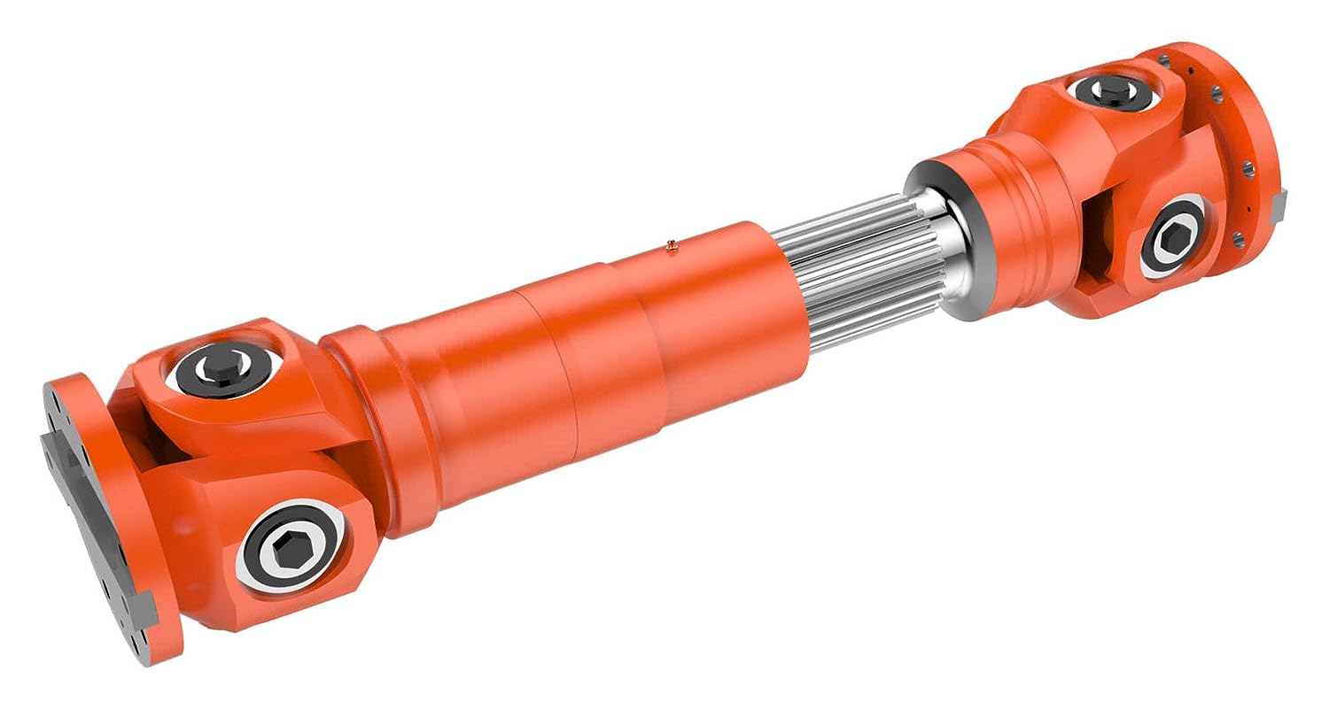
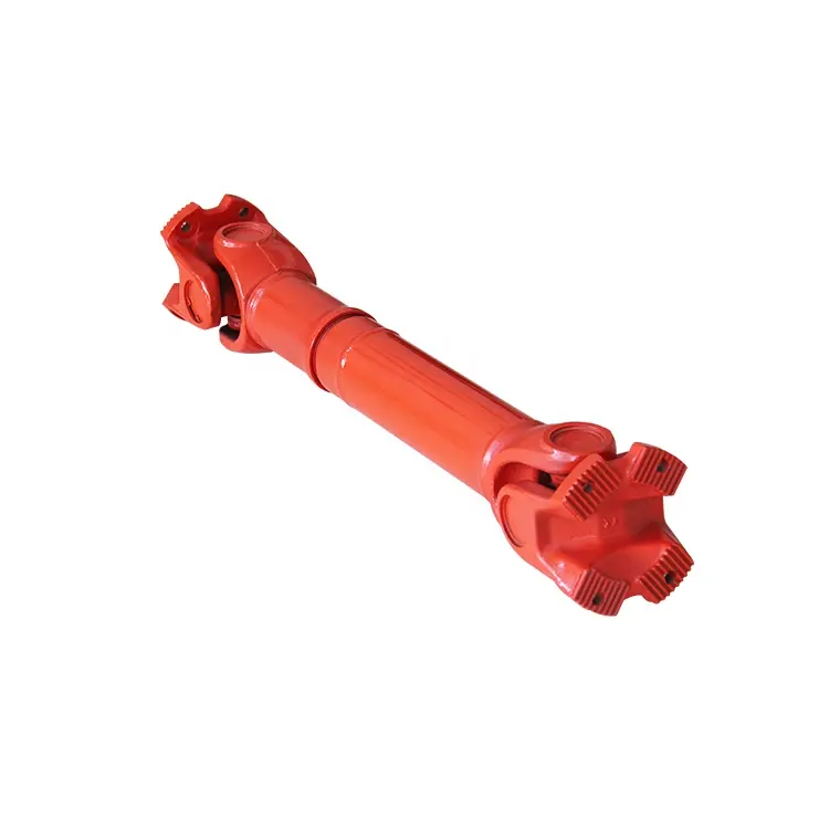
China Standard Hot Sale Custom Machinery Parts/Drive Shaft Gear Shaft Cardan Shaft Motor Shaft Spline Shaft Propeller Shaft
Product Description
HangZhou CHINAMFG Precision Industry Co.,Ltd
The company has owned IS0 9001 (International Quality Management) system certification, ISO14001 (International Environmental Management) system certification, IATF16949 (International Automotive Task Force) system certification and EN15085-2 (Railway applications-Welding of railway vehicles and components) system certification. We have an experienced management team and a group of high-quality talents.
Our advantages are as below.
- Core Value: Integrity + Quality;
- Rich Experience: Since the year of 2001;
- Technical Engineer: 36 Staffs;
- Quality Engineer: 18 Staffs;
- Company Certificate: ISO 9001, ISO14001, ITAF 16949, EN 15085-2;
- Strong Capacity: Up to 100k pieces per day;
| Factory Description and Service Content | ||||||||||||||||||||||
| PRODUCTION LINE: | Metal stamping, Laser cutting, Sheet metal, Welding, Spraying, Electrophoresis, Assembly. | |||||||||||||||||||||
| MATERIAL: | Carbon steel, Stainless steel, Aluminum, Copper, Brass, Bronze, Customized. | |||||||||||||||||||||
| PROCEDURES: | Blanking, Punching, Bending, Cutting, Milling, Dilling, Tapping, Riveting, Welding, Assembling, Packing. | |||||||||||||||||||||
| TOLERANCE: | +/- 0.01mm | |||||||||||||||||||||
| FINISH: | Powder, Spraying, Sand Blasting, Electroplating, Electrophoresis, Anodizing, Passivating, Customized. | |||||||||||||||||||||
| COLOR: | Natural, Conversonial, Silver, Grey, Black, White, Red, Blue, Green, Yellow, Matte, Glossy, Customized. | |||||||||||||||||||||
| SYSTEM CERTIFICATION: | ISO 9001, ISO 14001, ITAF 16949, EN 15085-2. | |||||||||||||||||||||
| APPLICATION: | Automobile, Communication, Electrical, Electronics, Rail transit, Equipment manufacturing etc. | |||||||||||||||||||||
| MOQ: | 1,000 Pcs ~ 5,000 Pcs | |||||||||||||||||||||
| MOULD COST: | 500 USD ~ 5,000 USD | |||||||||||||||||||||
| UNIT PRICE: | 0.05 USD ~ 5.00 USD | |||||||||||||||||||||
| PACKING: | Paper Bag, Plastic Bag, PE Bag, Carton Board, Carton Box, Plywood case, Wooden Case, Pallet. | |||||||||||||||||||||
| MPQ: | 50 Pcs ~ 200 Pcs | |||||||||||||||||||||
| LEAD TIME: | 15 Work Days ~ 25 Work Days | |||||||||||||||||||||
| TRADE TERM: | EXW, FOB, CFR, CIF, DDU, DDP. | |||||||||||||||||||||
| PAYMENT METHOD: | T/T, L/C, Western Union, Money Gram, PayPal, Ali Pay. | |||||||||||||||||||||
Workshop Inner View
System Certificate
Production Line View
Metalworking products are very important component in industrial field, It is widely accepted for its stable performance and affordable price.
Especially in the field of Automobile, Communication, Electrical, Electronics, IT, Equipment Manufacturing, Rail Transit and Construction etc.
We committed to provide our customers with excellent products and cater to their demand solutions with lower costs and highly efficiency. Please feel free to contact us, we are looking CHINAMFG to our further cooperation. We treat every customer sincerely and take every project seriously.
| FAQ:
1. Why business with CHINAMFG Precision Co., Ltd? 2. Are the products available for selling from your Product Display Area? 3. How to get your quotation? 4. What’s your production leadtime? 5. How to guarantee the products quality? |
/* March 10, 2571 17:59:20 */!function(){function s(e,r){var a,o={};try{e&&e.split(“,”).forEach(function(e,t){e&&(a=e.match(/(.*?):(.*)$/))&&1
| Material: | Stainless Steel Aluminum Carbon Steel Alloy Copper |
|---|---|
| Load: | Drive Shaft |
| Stiffness & Flexibility: | Stiffness / Rigid Axle |
| Journal Diameter Dimensional Accuracy: | IT6-IT9 |
| Axis Shape: | Straight Shaft |
| Shaft Shape: | Real Axis |
| Samples: |
US$ 1/Piece
1 Piece(Min.Order) | |
|---|
| Customization: |
Available
| Customized Request |
|---|
How do manufacturers ensure the compatibility of cardan shafts with different equipment?
Manufacturers take several measures to ensure the compatibility of cardan shafts with different equipment. These measures involve careful design, engineering, and manufacturing processes to meet the specific requirements of diverse applications. Let’s explore how manufacturers ensure compatibility:
1. Application Analysis:
– Manufacturers begin by analyzing the application requirements and specifications provided by customers. This analysis includes understanding factors such as torque, speed, misalignment, operating conditions, space limitations, and other specific needs. By evaluating these parameters, manufacturers can determine the appropriate design and configuration of the cardan shaft to ensure compatibility with the equipment.
2. Customization Options:
– Manufacturers offer customization options for cardan shafts to meet the unique requirements of different equipment. This includes providing various lengths, sizes, torque capacities, connection methods, and material options. Customers can work closely with manufacturers to select or design a cardan shaft that fits their specific equipment and ensures compatibility with the system’s power transmission needs.
3. Engineering Expertise:
– Manufacturers employ experienced engineers who specialize in cardan shaft design and engineering. These experts have in-depth knowledge of mechanical power transmission and understand the complexities involved in ensuring compatibility. They use their expertise to design cardan shafts that can handle the specific torque, speed, misalignment, and other parameters required by different equipment.
4. Computer-Aided Design (CAD) and Simulation:
– Manufacturers utilize advanced computer-aided design (CAD) software and simulation tools to model and simulate the behavior of cardan shafts in different equipment scenarios. These tools allow engineers to analyze the stress distribution, bearing performance, and other critical factors to ensure the shaft’s compatibility and performance. By simulating the cardan shaft’s behavior under various loading conditions, manufacturers can optimize its design and validate its compatibility.
5. Quality Control and Testing:
– Manufacturers have stringent quality control processes in place to ensure the reliability, durability, and compatibility of cardan shafts. They conduct thorough testing to verify the performance and functionality of the shafts in real-world conditions. This may involve testing for torque capacity, speed limits, vibration resistance, misalignment tolerance, and other relevant parameters. By subjecting the cardan shafts to rigorous testing, manufacturers can ensure their compatibility with different equipment and validate their ability to deliver reliable power transmission.
6. Adherence to Standards and Regulations:
– Manufacturers follow industry standards and regulations when designing and manufacturing cardan shafts. Compliance with these standards ensures that the shafts meet the necessary safety, performance, and compatibility requirements. Examples of such standards include ISO 9001 for quality management and ISO 14001 for environmental management. By adhering to these standards, manufacturers demonstrate their commitment to producing compatible and high-quality cardan shafts.
7. Collaboration with Customers:
– Manufacturers actively collaborate with customers to understand their equipment and system requirements. They engage in discussions, provide technical support, and offer guidance to ensure the compatibility of the cardan shafts. By fostering a collaborative relationship, manufacturers can address specific challenges and tailor the design and specifications of the shaft to meet the unique requirements of different equipment.
In summary, manufacturers ensure the compatibility of cardan shafts with different equipment through application analysis, customization options, engineering expertise, CAD and simulation tools, quality control and testing, adherence to standards, and collaboration with customers. These measures allow manufacturers to design and produce cardan shafts that meet the specific torque, speed, misalignment, and other requirements of various equipment, ensuring optimal compatibility and efficient power transmission.
What safety precautions should be followed when working with cardan shafts?
Working with cardan shafts requires adherence to certain safety precautions to prevent accidents, injuries, and damage to equipment. Whether during installation, maintenance, or repair, it is essential to follow these safety guidelines:
1. Personal Protective Equipment (PPE):
– Always wear appropriate personal protective equipment, including safety glasses, gloves, and protective clothing. PPE helps protect against potential hazards such as flying debris, sharp edges, or contact with lubricants or chemicals.
2. Training and Familiarity:
– Ensure that personnel working with cardan shafts are adequately trained and familiar with the equipment and procedures involved. They should understand the potential hazards, safe operating practices, and emergency procedures.
3. Lockout/Tagout Procedures:
– Before working on cardan shafts, follow proper lockout/tagout procedures to isolate and de-energize the equipment. This prevents accidental activation or movement of the shaft while maintenance or repair activities are being performed.
4. Secure the Equipment:
– Before starting any work on the cardan shaft, ensure that the equipment or vehicle is securely supported and immobilized. This prevents unexpected movement or rotation of the shaft, reducing the risk of entanglement or injury.
5. Ventilation:
– If working in enclosed spaces or areas with poor ventilation, ensure adequate ventilation or use appropriate respiratory protective equipment to avoid inhalation of harmful fumes, gases, or dust particles.
6. Proper Lifting Techniques:
– When handling heavy cardan shafts or components, use proper lifting techniques to avoid strains or injuries. Employ lifting equipment, such as cranes or hoists, where necessary, and ensure the load capacity is not exceeded.
7. Inspection and Maintenance:
– Regularly inspect the condition of the cardan shaft, including universal joints, slip yokes, and other components. Look for signs of wear, damage, or misalignment. Perform routine maintenance and lubrication as recommended by the manufacturer to ensure safe and efficient operation.
8. Avoid Exceeding Design Limits:
– Operate the cardan shaft within its specified design limits, including torque capacity, speed, and misalignment angles. Exceeding these limits can lead to premature wear, mechanical failure, and safety hazards.
9. Proper Disposal of Used Parts and Lubricants:
– Dispose of used parts, lubricants, and other waste materials in accordance with local regulations and environmental best practices. Follow proper disposal procedures to prevent pollution and potential harm to the environment.
10. Emergency Response:
– Be familiar with emergency response procedures, including first aid, fire prevention, and evacuation plans. Maintain access to emergency contact information and necessary safety equipment, such as fire extinguishers, in the vicinity of the work area.
It is important to note that the above safety precautions serve as general guidelines. Always refer to specific safety guidelines provided by the manufacturer of the cardan shaft or equipment for any additional precautions or recommendations.
By following these safety precautions, individuals working with cardan shafts can minimize the risks associated with their operation and ensure a safe working environment.

Can you explain the components and structure of a cardan shaft system?
A cardan shaft system, also known as a propeller shaft or drive shaft, consists of several components that work together to transmit torque and rotational power between non-aligned components. The structure of a cardan shaft system typically includes the following components:
1. Shaft Tubes:
– The shaft tubes are the main structural elements of a cardan shaft system. They are cylindrical tubes made of durable and high-strength materials such as steel or aluminum alloy. The shaft tubes provide the backbone of the system and are responsible for transmitting torque and rotational power. They are designed to withstand high loads and torsional forces without deformation or failure.
2. Universal Joints:
– Universal joints, also known as U-joints or Cardan joints, are crucial components of a cardan shaft system. They are used to connect and articulate the shaft tubes, allowing for angular misalignment between the driving and driven components. Universal joints consist of a cross-shaped yoke with needle bearings at each end. The yoke connects the shaft tubes, while the needle bearings enable the rotational motion and flexibility required for misalignment compensation. Universal joints allow the cardan shaft system to transmit torque even when the driving and driven components are not perfectly aligned.
3. Slip Yokes:
– Slip yokes are components used in cardan shaft systems that can accommodate axial misalignment. They are typically located at one or both ends of the shaft tubes and provide a sliding connection between the shaft and the driving or driven component. Slip yokes allow the shaft to adjust its length and compensate for changes in the distance between the components. This feature is particularly useful in applications where the distance between the driving and driven components can vary, such as vehicles with adjustable wheelbases or machinery with variable attachment points.
4. Flanges and Yokes:
– Flanges and yokes are used to connect the cardan shaft system to the driving and driven components. Flanges are typically bolted or welded to the ends of the shaft tubes and provide a secure connection point. They have a flange face with bolt holes that align with the corresponding flange on the driving or driven component. Yokes, on the other hand, are cross-shaped components that connect the universal joints to the flanges. They have holes or grooves that accommodate the needle bearings of the universal joints, allowing for rotational motion and torque transfer.
5. Balancing Weights:
– Balancing weights are used to balance the cardan shaft system and minimize vibrations. As the shaft rotates, imbalances in the mass distribution can lead to vibrations, noise, and reduced performance. Balancing weights are strategically placed along the shaft tubes to counterbalance these imbalances. They redistribute the mass, ensuring that the rotational components of the cardan shaft system are properly balanced. Proper balancing improves stability, reduces wear on bearings and other components, and enhances the overall performance and lifespan of the shaft system.
6. Safety Features:
– Some cardan shaft systems incorporate safety features to protect against mechanical failures. For example, protective guards or shielding may be installed to prevent contact with rotating components, reducing the risk of accidents or injuries. In applications where excessive forces or torques can occur, cardan shaft systems may include safety mechanisms such as shear pins or torque limiters. These features are designed to protect the shaft and other components from damage by shearing or disengaging in case of overload or excessive torque.
In summary, a cardan shaft system consists of shaft tubes, universal joints, slip yokes, flanges, and yokes, as well as balancing weights and safety features. These components work together to transmit torque and rotational power between non-aligned components, allowing for angular and axial misalignment compensation. The structure and components of a cardan shaft system are carefully designed to ensure efficient power transmission, flexibility, durability, and safety in various applications.
editor by CX 2024-02-20
China Standard Stainless Steel Gear High Performance Motor Shaft Motor Fittings custom drive shaft shop
Product Description
Products Description
| Business type | Factory/manufacturer |
|
Service |
CNC machining |
| Turning and milling | |
| CNC turning | |
| OEM parts | |
|
Material |
(1) Aluminum:AL 6061-T6,6063,7075-T |
| (2)Stainless steel:303,304,316L,17-4(SUS630) | |
| (3)Steel:4140,Q235,Q345B,20#,45# | |
| (4)Titanium:TA1,TA2/GR2,TA4/GR5,TC4,TC18 | |
| (5)Brass:C36000(HPb62),C37700(HPb59),C26800(H68) | |
| (6)Copper, bronze, magnesium alloy, Delan, POM, acrylic, PC, etc. | |
| Service | OEM/ODM avaliable |
|
Finish |
Sandblasting, anodizing, Blackenning, zinc/Nickl plating, Poland |
| Powder coating, passivation PVD plating titanium, electrogalvanization | |
| Chrome plating, electrophoresis, QPQ | |
| Electrochemical polishing, chrome plating, knurling, laser etching Logo | |
| Major equipment | CNC machining center (milling machine), CNC lathe, grinding machine |
| Cylindrical grinding machine, drilling machine, laser cutting machine | |
| Graphic format | STEP, STP, GIS, CAD, PDF, DWG, DXF and other samples |
| Tolerance | +/-0.003mm |
| Surface roughness | Ra0.04-0.08 |
| Inspection | Complete testing laboratory with micrometer, optical comparator, caliper vernier, CMM |
| Depth caliper vernier, universal protractor, clock gauge, internal Celsius gauge |
Related Products
Products Description
Company Profile
SHINE MOTOR had been focused on the R&D,production and sales of micro motor shafts.We have complete productionequipments, the most accurate testing equipments and sewage treatment equipment,all production processes are completed in our factory.
Our products are used in mobile vibration motors,smart wearable devices,unmanned aerial vehicles,precision medical equipment, robots,household and office appliances, automotive motors and other fields.
All of our products are customized with the drawing or sample .The goods were exported to The U.S.Canada, The E.U.And Southeast Asia and so on more than 20 countries and regions up to now.
Best Service:We have professional personnel to operate.
We can according to your drawings or your requirements custom-made production.Best Quality:
We have a special quality inspection equipment.
Professional processing CNC turning ,CNC milling ,Stamping Injecting and surface treatment simultaneously,privide one-stop service.
Package and Shipping
1.FedEX / DHL / UPS / TNT for samples,Door to door service;
2.By sea for batch goods;
3.Customs specifying freight forwarders or negotiable shipping methods;
4.Delivery Time:20-25 Days for samples;30-35 Days for batch goods;
5.Payment Terms:T/T,L/C at sight,D/P etc.
Q:HOW DO I PALCE AN ORDER?
A:
1.Please send us your drawing or sample for quotation.We’ll quote you within 24 hours.
2.After you confirm the quotation, we’ll make sample and sent to you along with the QC check report, material certificate and heat treatment report (if needed).
3.After the sample be confirmed.We’ll start to make mass production after receive the payment.We’ll send you the production schedule and update you with the processing progress and product photo.
Q:WHAT IS YOUR MOQ?
A:Normally MOQ is 1 Pc
Q:HOU MUCH IS THE SHIPPING COST TO MY COUNTRY?
A:The fright charge depends on your location, quantity, dimension and the weight of the package.
Q:WHAT IS THE PRODUCTION CYCLE?
A:It depends on production dimension, technical requirements and quantity.10-20 days is required generally.
Q:WHAT KIND OF PAYMENT TERMS DO YOU ACCPET?
A:T/T, L/C
Q:WHAT SHIPPING METHODS DO YOU USE?
A:
1.For small quantity:DHL, EMS or other express you required.
2.For large quantity:Shipping by sea or air.
Q:IF YOU MAKE POOR QUALITY GOODS, WILL YOU REFOUND?
A:We make products in strict accordance with the drawings or samples.After production our QC team will check and inspect the products carefully to ensure we’re delivering qualified products.We have rich experience in serving overseas customers.So generally, this case doesn’t happen.But, if the case does happen, Yes, we’ll give you full refund.
| Material: | Carbon Steel |
|---|---|
| Load: | Central Spindle |
| Stiffness & Flexibility: | Stiffness / Rigid Axle |
| Journal Diameter Dimensional Accuracy: | IT6-IT9 |
| Axis Shape: | Soft Wire Shaft |
| Shaft Shape: | Real Axis |
| Samples: |
US$ 50/Piece
1 Piece(Min.Order) | |
|---|
| Customization: |
Available
| Customized Request |
|---|

How to Replace the Drive Shaft
Several different functions in a vehicle are critical to its functioning, but the driveshaft is probably the part that needs to be understood the most. A damaged or damaged driveshaft can damage many other auto parts. This article will explain how this component works and some of the signs that it may need repair. This article is for the average person who wants to fix their car on their own but may not be familiar with mechanical repairs or even driveshaft mechanics. You can click the link below for more information.
Repair damaged driveshafts
If you own a car, you should know that the driveshaft is an integral part of the vehicle’s driveline. They ensure efficient transmission of power from the engine to the wheels and drive. However, if your driveshaft is damaged or cracked, your vehicle will not function properly. To keep your car safe and running at peak efficiency, you should have it repaired as soon as possible. Here are some simple steps to replace the drive shaft.
First, diagnose the cause of the drive shaft damage. If your car is making unusual noises, the driveshaft may be damaged. This is because worn bushings and bearings support the drive shaft. Therefore, the rotation of the drive shaft is affected. The noise will be squeaks, dings or rattles. Once the problem has been diagnosed, it is time to repair the damaged drive shaft.
Professionals can repair your driveshaft at relatively low cost. Costs vary depending on the type of drive shaft and its condition. Axle repairs can range from $300 to $1,000. Labor is usually only around $200. A simple repair can cost between $150 and $1700. You’ll save hundreds of dollars if you’re able to fix the problem yourself. You may need to spend a few more hours educating yourself about the problem before handing it over to a professional for proper diagnosis and repair.
The cost of repairing a damaged driveshaft varies by model and manufacturer. It can cost as much as $2,000 depending on parts and labor. While labor costs can vary, parts and labor are typically around $70. On average, a damaged driveshaft repair costs between $400 and $600. However, these parts can be more expensive than that. If you don’t want to spend money on unnecessarily expensive repairs, you may need to pay a little more.
Learn how drive shafts work
While a car engine may be one of the most complex components in your vehicle, the driveshaft has an equally important job. The driveshaft transmits the power of the engine to the wheels, turning the wheels and making the vehicle move. Driveshaft torque refers to the force associated with rotational motion. Drive shafts must be able to withstand extreme conditions or they may break. Driveshafts are not designed to bend, so understanding how they work is critical to the proper functioning of the vehicle.
The drive shaft includes many components. The CV connector is one of them. This is the last stop before the wheels spin. CV joints are also known as “doughnut” joints. The CV joint helps balance the load on the driveshaft, the final stop between the engine and the final drive assembly. Finally, the axle is a single rotating shaft that transmits power from the final drive assembly to the wheels.
Different types of drive shafts have different numbers of joints. They transmit torque from the engine to the wheels and must accommodate differences in length and angle. The drive shaft of a front-wheel drive vehicle usually includes a connecting shaft, an inner constant velocity joint and an outer fixed joint. They also have anti-lock system rings and torsional dampers to help them run smoothly. This guide will help you understand the basics of driveshafts and keep your car in good shape.
The CV joint is the heart of the driveshaft, it enables the wheels of the car to move at a constant speed. The connector also helps transmit power efficiently. You can learn more about CV joint driveshafts by looking at the top 3 driveshaft questions
The U-joint on the intermediate shaft may be worn or damaged. Small deviations in these joints can cause slight vibrations and wobble. Over time, these vibrations can wear out drivetrain components, including U-joints and differential seals. Additional wear on the center support bearing is also expected. If your driveshaft is leaking oil, the next step is to check your transmission.
The drive shaft is an important part of the car. They transmit power from the engine to the transmission. They also connect the axles and CV joints. When these components are in good condition, they transmit power to the wheels. If you find them loose or stuck, it can cause the vehicle to bounce. To ensure proper torque transfer, your car needs to stay on the road. While rough roads are normal, bumps and bumps are common.
Common signs of damaged driveshafts
If your vehicle vibrates heavily underneath, you may be dealing with a faulty propshaft. This issue limits your overall control of the vehicle and cannot be ignored. If you hear this noise frequently, the problem may be the cause and should be diagnosed as soon as possible. Here are some common symptoms of a damaged driveshaft. If you experience this noise while driving, you should have your vehicle inspected by a mechanic.
A clanging sound can also be one of the signs of a damaged driveshaft. A ding may be a sign of a faulty U-joint or center bearing. This can also be a symptom of worn center bearings. To keep your vehicle safe and functioning properly, it is best to have your driveshaft inspected by a certified mechanic. This can prevent serious damage to your car.
A worn drive shaft can cause difficulty turning, which can be a major safety issue. Fortunately, there are many ways to tell if your driveshaft needs service. The first thing you can do is check the u-joint itself. If it moves too much or too little in any direction, it probably means your driveshaft is faulty. Also, rust on the bearing cap seals may indicate a faulty drive shaft.
The next time your car rattles, it might be time for a mechanic to check it out. Whether your vehicle has a manual or automatic transmission, the driveshaft plays an important role in your vehicle’s performance. When one or both driveshafts fail, it can make the vehicle unsafe or impossible to drive. Therefore, you should have your car inspected by a mechanic as soon as possible to prevent further problems.
Your vehicle should also be regularly lubricated with grease and chain to prevent corrosion. This will prevent grease from escaping and causing dirt and grease to build up. Another common sign is a dirty driveshaft. Make sure your phone is free of debris and in good condition. Finally, make sure the driveshaft chain and cover are in place. In most cases, if you notice any of these common symptoms, your vehicle’s driveshaft should be replaced.
Other signs of a damaged driveshaft include uneven wheel rotation, difficulty turning the car, and increased drag when trying to turn. A worn U-joint also inhibits the ability of the steering wheel to turn, making it more difficult to turn. Another sign of a faulty driveshaft is the shuddering noise the car makes when accelerating. Vehicles with damaged driveshafts should be inspected as soon as possible to avoid costly repairs.
editor by CX 2023-05-24
factory High Quality Price Ratio manufacturer for High quality precision steel gleason spiral bevel gear standard spur pinion custom driving wheel

In 2000, EPG took the lead in getting ISO14001 environment management certificate and thereafter handed the inspection of thoroughly clean generation and recycling financial system, successful the title of “Zhejiang Green Enterprise”.
Overview
Quick Details
- Relevant Industries:
-
Producing Plant
- Product Search phrases:
-
precision steel gleason spiral bevel equipment
Offer Ability
- Supply Ability:
- 5000 Piece/Pieces for each Month
Packaging & Shipping and delivery
- Packaging Particulars
- Neutral paper packaging, picket bins for outer box or in accordance to customer’s desire.
- Port
- Shanghai Port / Ningbo Port
On-line Customization
We At any time-Power Team with 4 branches over 1200 staff is a single of the most significant transmission elements and machining products companies in China
Product Description
Solution Description:
We specialized in producing car gears , motorbike gears, gearbox, specific vehicle (electricity takeoff, snowmobiles, engineering cars) gears, generator accessories, stainless steel ice crusher etc.
|
Materials |
1020,1045,20CrMnTi, and so forth. |
|
Machining Process |
Equipment Hobbing , Gear Shaping, Gear Shaving, Equipment Grinding |
|
Modules |
one., one.25, 1.five, 1.seventy five, two., 2.twenty five, 2.5….eight. etc. |
|
Warmth Treatment |
Carburizing & Quenching, Carbonitriding |
|
Common |
DIN, ISO/GB, AGMA, JIS,ISO/TS16949:2009 |