Product Description
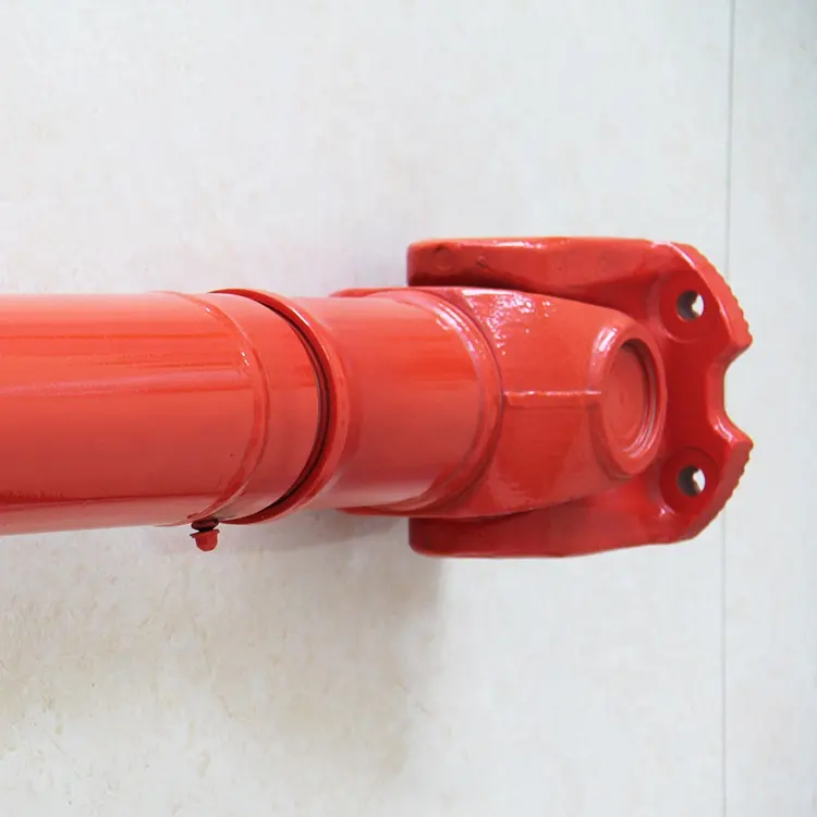
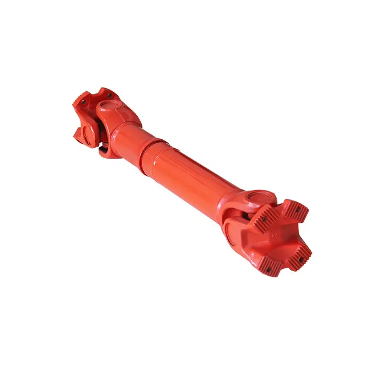
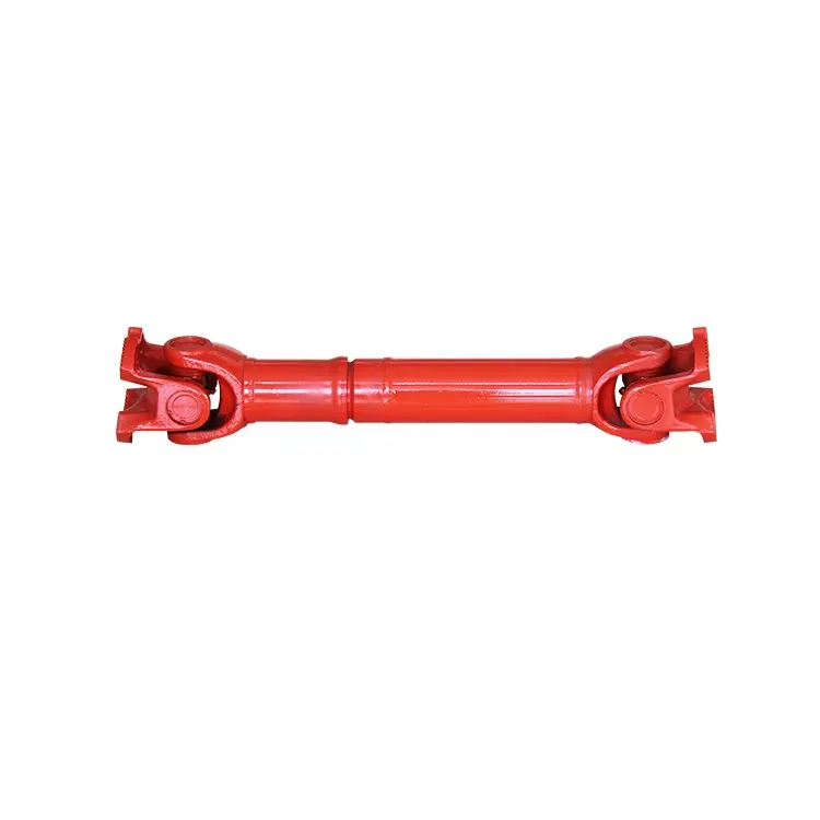
| Product Name | Cardan Shaft |
| Product Model | SWC-I75A-335+40 |
| Main Material | 35CrMo or 45# Steel |
| Nominal Torque | 500 N.M |
| Normal Length | 335 mm |
| Length Compensation | 40 mm |
/* January 22, 2571 19:08:37 */!function(){function s(e,r){var a,o={};try{e&&e.split(“,”).forEach(function(e,t){e&&(a=e.match(/(.*?):(.*)$/))&&1
| Standard Or Nonstandard: | Nonstandard |
|---|---|
| Shaft Hole: | 19-32 |
| Torque: | >80N.M |
| Samples: |
US$ 10/Piece
1 Piece(Min.Order) | Order Sample |
|---|
| Customization: |
Available
| Customized Request |
|---|
.shipping-cost-tm .tm-status-off{background: none;padding:0;color: #1470cc}
| Shipping Cost:
Estimated freight per unit. |
about shipping cost and estimated delivery time. |
|---|
| Payment Method: |
|
|---|---|
|
Initial Payment Full Payment |
| Currency: | US$ |
|---|
| Return&refunds: | You can apply for a refund up to 30 days after receipt of the products. |
|---|
What maintenance practices are essential for prolonging the lifespan of cardan shafts?
Maintaining proper maintenance practices is crucial for prolonging the lifespan of cardan shafts and ensuring their optimal performance. Here are some essential maintenance practices to consider:
1. Regular Lubrication:
– Proper lubrication of the cardan shaft’s universal joints is vital for reducing friction, preventing wear, and ensuring smooth operation. Regularly lubricate the universal joints according to the manufacturer’s recommendations using the appropriate lubricant. This helps to minimize frictional losses, extend the life of the needle bearings, and maintain the efficiency of power transfer.
2. Inspection and Cleaning:
– Regular inspection and cleaning of the cardan shaft are essential for identifying any signs of wear, damage, or misalignment. Inspect the shaft for any cracks, corrosion, or excessive play in the universal joints. Clean the shaft periodically to remove dirt, debris, and contaminants that could potentially cause damage or hinder proper operation.
3. Misalignment Adjustment:
– Check for any misalignment between the driving and driven components connected by the cardan shaft. If misalignment is detected, address it promptly by adjusting the alignment or replacing any worn or damaged components. Misalignment can lead to increased stress on the shaft and its components, resulting in premature wear and reduced lifespan.
4. Balancing:
– Periodically check the balance of the cardan shaft to ensure smooth operation and minimize vibration. If any imbalance is detected, consult with a qualified technician to rebalance the shaft or replace any components that may be causing the imbalance. Balanced cardan shafts promote efficient power transfer and reduce stress on the drivetrain.
5. Torque and RPM Monitoring:
– Keep track of the torque and RPM (revolutions per minute) values during operation. Ensure that the cardan shaft is not subjected to torque levels exceeding its design capacity, as this can lead to premature failure. Similarly, avoid operating the shaft at speeds beyond its recommended RPM range. Monitoring torque and RPM helps prevent excessive stress and ensures the longevity of the shaft.
6. Periodic Replacement:
– Despite regular maintenance, cardan shafts may eventually reach the end of their service life due to normal wear and tear. Periodically assess the condition of the shaft and its components, considering factors such as mileage, operating conditions, and manufacturer recommendations. If significant wear or damage is observed, it may be necessary to replace the cardan shaft to maintain optimal performance and safety.
7. Manufacturer Guidelines:
– Always refer to the manufacturer’s guidelines and recommendations for maintenance practices specific to your cardan shaft model. Manufacturers often provide detailed instructions regarding lubrication intervals, inspection procedures, and other maintenance requirements. Adhering to these guidelines ensures that the maintenance practices align with the manufacturer’s specifications, promoting the longevity of the cardan shaft.
By following these essential maintenance practices, you can prolong the lifespan of cardan shafts, optimize their performance, and minimize the likelihood of unexpected failures. Regular maintenance not only extends the life of the cardan shaft but also contributes to the overall efficiency and reliability of the systems in which they are utilized.

How do cardan shafts handle variations in load, speed, and misalignment during operation?
Cardan shafts are designed to handle variations in load, speed, and misalignment during operation. They incorporate specific features and mechanisms to accommodate these factors and ensure efficient power transmission. Let’s explore how cardan shafts handle these variations:
1. Load Variation:
– Cardan shafts are designed to transmit torque and handle variations in load. The torque capacity of the shaft is determined based on the application’s requirements, and the shaft is manufactured using materials and dimensions that can withstand the specified loads. The design and construction of the shaft, including the selection of universal joints and slip yokes, are optimized to handle the anticipated loads. By choosing appropriate material strengths and dimensions, cardan shafts can effectively transmit varying loads without failure or excessive deflection.
2. Speed Variation:
– Cardan shafts can accommodate variations in rotational speed between the driving and driven components. The universal joints, which connect the shaft’s segments, allow for angular movement, thereby compensating for speed differences. The design of the universal joints and the use of needle bearings or roller bearings enable smooth rotation and efficient power transmission even at varying speeds. However, it’s important to note that excessively high speeds can introduce additional challenges such as increased vibration and wear, which may require additional measures such as balancing and lubrication.
3. Misalignment Compensation:
– Cardan shafts are specifically designed to handle misalignment between the driving and driven components. They can accommodate angular misalignment, parallel offset, and axial displacement to a certain extent. The universal joints in the shaft assembly allow for flexibility and articulation, enabling the shaft to transmit torque even when the components are not perfectly aligned. The design of the universal joints, along with their bearing arrangements and seals, allows for smooth rotation and compensation of misalignment. Manufacturers specify the maximum allowable misalignment angles and displacements for cardan shafts, and exceeding these limits can lead to increased wear, vibration, and reduced efficiency.
4. Telescopic Design:
– Cardan shafts often feature a telescopic design, which allows for axial movement and adjustment to accommodate variations in distance between the driving and driven components. This telescopic design enables the shaft to handle changes in length during operation, such as when the vehicle or equipment undergoes suspension movement or when the drivetrain components experience positional changes. The telescopic mechanism ensures that the shaft remains properly connected and engaged, maintaining power transmission efficiency even when there are fluctuations in distance or position.
5. Regular Maintenance:
– To ensure optimal performance and longevity, cardan shafts require regular maintenance. This includes inspections, lubrication of universal joints and slip yokes, and monitoring for wear or damage. Regular maintenance helps identify and address any issues related to load, speed, or misalignment variations, ensuring that the shaft continues to function effectively under changing operating conditions.
Overall, cardan shafts handle variations in load, speed, and misalignment through their design features such as universal joints, telescopic design, and flexibility. By incorporating these elements, along with proper material selection, lubrication, and maintenance practices, cardan shafts can reliably transmit torque and accommodate the changing operating conditions in vehicles and equipment.

How do cardan shafts contribute to power transmission and motion in various applications?
Cardan shafts, also known as propeller shafts or drive shafts, play a significant role in power transmission and motion in various applications. They are widely used in automotive, industrial, and marine sectors to transfer torque and rotational power between non-aligned components. Cardan shafts offer several benefits that contribute to efficient power transmission and enable smooth motion in different applications. Here’s a detailed look at how cardan shafts contribute to power transmission and motion:
1. Torque Transmission:
– Cardan shafts are designed to transmit torque from a driving source, such as an engine or motor, to a driven component, such as wheels, propellers, or machinery. They can handle high torque loads and transfer power over long distances. By connecting the driving and driven components, cardan shafts ensure the efficient transmission of rotational power, enabling the motion of vehicles, machinery, or equipment.
2. Angular Misalignment Compensation:
– One of the key advantages of cardan shafts is their ability to accommodate angular misalignment between the driving and driven components. The universal joints present in cardan shafts allow for flexibility and articulation, compensating for variations in the relative positions of the components. This flexibility is crucial in applications where the driving and driven components may not be perfectly aligned, such as vehicles with suspension movement or machinery with adjustable parts. The cardan shaft’s universal joints enable the transmission of torque even when there are angular deviations, ensuring smooth power transfer.
3. Axial Misalignment Compensation:
– In addition to angular misalignment compensation, cardan shafts can also accommodate axial misalignment between the driving and driven components. Axial misalignment refers to the displacement along the axis of the shafts. The design of cardan shafts with telescopic sections or sliding splines allows for axial movement, enabling the shaft to adjust its length to compensate for variations in the distance between the components. This feature is particularly useful in applications where the distance between the driving and driven components can change, such as vehicles with adjustable wheelbases or machinery with variable attachment points.
4. Vibration Damping:
– Cardan shafts contribute to vibration damping in various applications. The flexibility provided by the universal joints helps absorb and dampen vibrations generated during operation. By allowing slight angular deflection and accommodating misalignment, cardan shafts help reduce the transmission of vibrations from the driving source to the driven component. This vibration damping feature improves the overall smoothness of operation, enhances ride comfort in vehicles, and reduces stress on machinery.
5. Balancing:
– To ensure smooth and efficient operation, cardan shafts are carefully balanced. Even minor imbalances in rotational components can result in vibration, noise, and reduced performance. Balancing the cardan shaft minimizes these issues by redistributing mass along the shaft, eliminating or minimizing vibrations caused by centrifugal forces. Proper balancing improves the overall stability, reduces wear on bearings and other components, and extends the lifespan of the shaft and associated equipment.
6. Safety Features:
– Cardan shafts often incorporate safety features to protect against mechanical failures. For example, some cardan shafts have guards or shielding to prevent contact with rotating components, reducing the risk of accidents or injuries. In applications where excessive forces or torques can occur, cardan shafts may include safety mechanisms such as shear pins or torque limiters. These features are designed to protect the shaft and other components from damage by shearing or disengaging in case of overload or excessive torque.
7. Versatility in Applications:
– Cardan shafts offer versatility in their applications. They are widely used in various industries, including automotive, agriculture, mining, marine, and industrial sectors. In automotive applications, cardan shafts transmit power from the engine to the wheels, enabling vehicle propulsion. In industrial machinery, they transfer power between motors and driven components such as conveyors, pumps, or generators. In marine applications, cardan shafts transmit power from the engine to propellers, enabling ship propulsion. The versatility of cardan shafts makes them suitable for a wide range of power transmission needs in different environments.
In summary, cardan shafts are essential components that contribute to efficient power transmission and motion in various applications. Their ability to accommodate angular and axial misalignment, dampen vibrations, balance rotational components, and incorporate safety features enables smooth and reliable operation in vehicles, machinery, and equipment. The versatility of cardan shafts makes them a valuable solution for transmitting torque and rotational power in diverse industries and environments.


editor by CX 2024-05-16
China Custom Cwf-C2304kja-17 Cardan Shaft for CZPT Noah
Product Description
Product Description
As a professional manufacturer for propeller shaft, we have +1000 items for all kinds of car, At present, our products are mainly sold in North America, Europe, Australia, South Korea, the Middle East and Southeast Asia and other regions, applicable models are European cars, American cars, Japanese and Korean cars, etc.
Our advantage:
1. Full range of products
2. MOQ qty: 1pcs/items
3. Delivery on time
4: Warranty: 1 YEAR
| OE NUMBER | 37110-28440 |
| TYPE | Toyota Noah CWF-C2304KJA-17 |
| MATERIAL | STEEL |
| BALANCE STHangZhouRD | G16,3200RMP |
/* January 22, 2571 19:08:37 */!function(){function s(e,r){var a,o={};try{e&&e.split(“,”).forEach(function(e,t){e&&(a=e.match(/(.*?):(.*)$/))&&1
| After-sales Service: | 1years |
|---|---|
| Condition: | New |
| Color: | Black |
| Customization: |
Available
| Customized Request |
|---|
.shipping-cost-tm .tm-status-off{background: none;padding:0;color: #1470cc}
|
Shipping Cost:
Estimated freight per unit. |
about shipping cost and estimated delivery time. |
|---|
| Payment Method: |
|
|---|---|
|
Initial Payment Full Payment |
| Currency: | US$ |
|---|
| Return&refunds: | You can apply for a refund up to 30 days after receipt of the products. |
|---|
How do cardan shafts handle variations in length and connection methods?
Cardan shafts are designed to handle variations in length and connection methods, allowing for flexibility in their installation and use. These shafts incorporate several features and mechanisms that enable them to accommodate different lengths and connection methods. Let’s explore how cardan shafts handle these variations:
1. Telescopic Design:
– Cardan shafts often employ a telescopic design, which consists of multiple sections that can slide in and out. These sections allow for adjustment of the overall length of the shaft to accommodate variations in distance between the driving and driven components. By telescoping the shaft, it can be extended or retracted as needed, ensuring proper alignment and power transmission.
2. Slip Yokes:
– Slip yokes are components used in cardan shafts that allow for axial movement. They are typically located at one or both ends of the telescopic sections. Slip yokes provide a sliding connection that compensates for changes in length and helps to maintain proper alignment between the driving and driven components. When the length of the shaft needs to change, the slip yokes slide along the shaft, allowing for the necessary adjustment without disrupting power transmission.
3. Flange Connections:
– Cardan shafts can utilize flange connections to attach the shaft to the driving and driven components. Flange connections provide a secure and rigid connection, ensuring efficient power transfer. The flanges are typically bolted or welded to the shaft and the corresponding components, such as the transmission, differential, or axle. Flange connections allow for easy installation and removal of the cardan shaft while maintaining stability and alignment.
4. Universal Joints:
– Universal joints, or U-joints, are essential components in cardan shafts that allow for angular misalignment between the driving and driven components. They consist of a cross-shaped yoke and needle bearings at each end. The universal joints provide flexibility and compensate for variations in angle and alignment. This flexibility enables cardan shafts to handle different connection methods, such as non-parallel or offset connections, while maintaining efficient power transmission.
5. Splined Connections:
– Some cardan shafts employ splined connections, where the shaft and the driving/driven components have matching splined profiles. Splined connections provide a precise and secure connection that allows for torque transmission while accommodating length variations. The splined profiles enable the shaft to slide in and out, adjusting the length as needed while maintaining a positive connection.
6. Customization and Adaptable Designs:
– Cardan shafts can be customized and designed to handle specific variations in length and connection methods based on the requirements of the application. Manufacturers offer a range of cardan shaft options with different lengths, sizes, and connection configurations. By collaborating with cardan shaft manufacturers and suppliers, engineers can select or design shafts that match the specific needs of their systems, ensuring optimal performance and compatibility.
In summary, cardan shafts handle variations in length and connection methods through telescopic designs, slip yokes, flange connections, universal joints, splined connections, and customizable designs. These features allow the shafts to adjust their length, compensate for misalignment, and establish secure connections while maintaining efficient power transmission. By incorporating these mechanisms, cardan shafts offer flexibility and adaptability in various applications where length variations and different connection methods are encountered.
What safety precautions should be followed when working with cardan shafts?
Working with cardan shafts requires adherence to certain safety precautions to prevent accidents, injuries, and damage to equipment. Whether during installation, maintenance, or repair, it is essential to follow these safety guidelines:
1. Personal Protective Equipment (PPE):
– Always wear appropriate personal protective equipment, including safety glasses, gloves, and protective clothing. PPE helps protect against potential hazards such as flying debris, sharp edges, or contact with lubricants or chemicals.
2. Training and Familiarity:
– Ensure that personnel working with cardan shafts are adequately trained and familiar with the equipment and procedures involved. They should understand the potential hazards, safe operating practices, and emergency procedures.
3. Lockout/Tagout Procedures:
– Before working on cardan shafts, follow proper lockout/tagout procedures to isolate and de-energize the equipment. This prevents accidental activation or movement of the shaft while maintenance or repair activities are being performed.
4. Secure the Equipment:
– Before starting any work on the cardan shaft, ensure that the equipment or vehicle is securely supported and immobilized. This prevents unexpected movement or rotation of the shaft, reducing the risk of entanglement or injury.
5. Ventilation:
– If working in enclosed spaces or areas with poor ventilation, ensure adequate ventilation or use appropriate respiratory protective equipment to avoid inhalation of harmful fumes, gases, or dust particles.
6. Proper Lifting Techniques:
– When handling heavy cardan shafts or components, use proper lifting techniques to avoid strains or injuries. Employ lifting equipment, such as cranes or hoists, where necessary, and ensure the load capacity is not exceeded.
7. Inspection and Maintenance:
– Regularly inspect the condition of the cardan shaft, including universal joints, slip yokes, and other components. Look for signs of wear, damage, or misalignment. Perform routine maintenance and lubrication as recommended by the manufacturer to ensure safe and efficient operation.
8. Avoid Exceeding Design Limits:
– Operate the cardan shaft within its specified design limits, including torque capacity, speed, and misalignment angles. Exceeding these limits can lead to premature wear, mechanical failure, and safety hazards.
9. Proper Disposal of Used Parts and Lubricants:
– Dispose of used parts, lubricants, and other waste materials in accordance with local regulations and environmental best practices. Follow proper disposal procedures to prevent pollution and potential harm to the environment.
10. Emergency Response:
– Be familiar with emergency response procedures, including first aid, fire prevention, and evacuation plans. Maintain access to emergency contact information and necessary safety equipment, such as fire extinguishers, in the vicinity of the work area.
It is important to note that the above safety precautions serve as general guidelines. Always refer to specific safety guidelines provided by the manufacturer of the cardan shaft or equipment for any additional precautions or recommendations.
By following these safety precautions, individuals working with cardan shafts can minimize the risks associated with their operation and ensure a safe working environment.
How do cardan shafts handle variations in angles, torque, and alignment?
Cardan shafts, also known as propeller shafts or drive shafts, are designed to handle variations in angles, torque, and alignment between the driving and driven components. They possess unique structural and mechanical features that enable them to accommodate these variations effectively. Let’s explore how cardan shafts handle each of these factors:
Variations in Angles:
– Cardan shafts are specifically designed to handle angular misalignment between the driving and driven components. This misalignment can occur due to factors such as changes in suspension height, flexing of the chassis, or uneven terrain. The universal joints used in cardan shafts allow for angular movement by employing a cross-shaped yoke with needle bearings at each end. These needle bearings facilitate the rotation and flexibility required to compensate for angular misalignment. As a result, the cardan shaft can maintain a consistent power transmission despite variations in angles, ensuring smooth and efficient operation.
Variations in Torque:
– Cardan shafts are engineered to withstand and transmit varying levels of torque. Torque variations may arise from changes in load, speed, or resistance encountered during operation. The robust construction of the shaft tubes, coupled with the use of universal joints and slip yokes, allows the cardan shaft to handle these torque fluctuations. The shaft tubes are typically made of durable and high-strength materials, such as steel or aluminum alloy, which can withstand high torsional forces without deformation or failure. Universal joints and slip yokes provide flexibility and allow the shaft to adjust its length, absorbing torque fluctuations and ensuring reliable power transmission.
Variations in Alignment:
– Cardan shafts are adept at compensating for misalignment between the driving and driven components that can occur due to manufacturing tolerances, assembly errors, or structural changes over time. The universal joints present in cardan shafts play a crucial role in accommodating misalignment. The needle bearings within the universal joints allow for slight axial movement, permitting misaligned components to remain connected without hindering torque transmission. Additionally, slip yokes, which are often incorporated into cardan shaft systems, provide axial adjustability, allowing the shaft to adapt to changes in the distance between the driving and driven components. This flexibility in alignment compensation ensures that the cardan shaft can effectively transmit power even when the components are not perfectly aligned.
Overall, cardan shafts handle variations in angles, torque, and alignment through the combination of universal joints, slip yokes, and robust shaft tube construction. These features allow the shaft to accommodate angular misalignment, absorb torque fluctuations, and compensate for changes in alignment. By providing flexibility and reliable power transmission, cardan shafts contribute to the smooth operation and longevity of various systems, including automotive drivetrains, industrial machinery, and marine propulsion systems.
editor by CX 2024-05-15
China Custom Agricultural Cardan Shafts Type and Cultivators Use Pto Shaft
Product Description
Specification OF PTO Drive Shaft —Speedway:
We developed and produced many tractor spare parts for Japanese Tractors .
Product Name: Japanese tractor transmission clutch disc parts for B1400 B7000
Tractor Model we can supply: B1500/1400,B5000,B6000, B7000, TU1400, TX1400, TX1500, YM F1401, YM1400 ETC.
The parts for example: Tyres, rim Jante, Kit coupling KB-TX 3 point linkage. Exhaust pipe Steering wheel. Kit coupling YM F14/F15, gear shaft, PTO shaft, PTO cardan, key, regulator ect.
Most of the spare parts are with stock. If you are interested in, please feel easy to contact me.
Other relevant parts for cars or machinery we have made in our workshop are as follows:
Drive shaft parts and assemblies,
Universal joint parts and assemblies,
PTO drive shafts,
Spline shafts,
Slip yokes,
Weld yokes,
Flange yokes,
Steering columns,
Connecting rods,
etc.
Product Description
Pto Drive Shaft Item:
| Item | Cross journal size | 540dak-rpm | 1000dak-rpm | |||
| Series 1 | 22mm | 54mm | 12KW | 16HP | 18KW | 25HP |
| Series 2 | 23.8mm | 61.3mm | 15KW | 21HP | 23KW | 31HP |
| Series 3 | 27mm | 70mm | 26KW | 35HP | 40KW | 55HP |
| Series 4 | 27mm | 74.6mm | 26KW | 35HP | 40KW | 55HP |
| Series 5 | 30.2mm | 80mm | 35KW | 47HP | 54KW | 74HP |
| Series 6 | 30.2mm | 92mm | 47KW | 64HP | 74KW | 100HP |
| Series 7 | 30.2mm | 106.5mm | 55KW | 75HP | 87KW | 18HP |
| Series 8 | 35mm | 106.5mm
|
70KW | 95HP | 110KW | 150HP |
| Series 38 | 38mm | 102mm | 70KW | 95HP | 110KW | 150HP |
Company Profile
Certifications
FAQ
/* January 22, 2571 19:08:37 */!function(){function s(e,r){var a,o={};try{e&&e.split(“,”).forEach(function(e,t){e&&(a=e.match(/(.*?):(.*)$/))&&1
| Type: | Shaft |
|---|---|
| Usage: | Agricultural Products Processing, Farmland Infrastructure, Harvester, Planting and Fertilization, Grain Threshing, Cleaning and Drying |
| Material: | Stainless Steel |
| Power Source: | Pto Dirven Shaft |
| Weight: | Standard |
| After-sales Service: | 1 Year |
| Samples: |
US$ 300/Piece
1 Piece(Min.Order) | |
|---|
How do cardan shafts ensure efficient power transfer while maintaining balance?
Cardan shafts are designed to ensure efficient power transfer while maintaining balance between the driving and driven components. They employ various mechanisms and features that contribute to both aspects. Let’s explore how cardan shafts achieve efficient power transfer and balance:
1. Universal Joints:
– Cardan shafts utilize universal joints, also known as U-joints, to transmit torque from the driving component to the driven component. Universal joints consist of a cross-shaped yoke with needle bearings at each end. These needle bearings allow the joints to pivot and accommodate angular misalignment between the driving and driven components. By allowing for flexibility in movement, universal joints ensure efficient power transfer even when the components are not perfectly aligned, minimizing energy losses and maintaining balance.
2. Misalignment Compensation:
– Cardan shafts are designed to compensate for misalignment between the driving and driven components. The universal joints, along with slip yokes and telescopic sections, allow the shaft to adjust its length and accommodate variations in alignment. This misalignment compensation capability ensures that the cardan shaft can transmit power smoothly and efficiently, reducing stress on the components and maintaining balance during operation.
3. Balanced Design:
– Cardan shafts are engineered with a balanced design to minimize vibration and maintain smooth operation. The shaft tubes are typically symmetrically constructed, and the universal joints are positioned to distribute the mass evenly. This balanced design helps to reduce vibration and minimize the occurrence of unbalanced forces that can negatively impact power transfer and overall system performance. By maintaining balance, cardan shafts contribute to efficient power transmission and improve the lifespan of the components involved.
4. High-Quality Materials and Manufacturing:
– The materials used in the construction of cardan shafts, such as steel or aluminum alloy, are carefully selected for their strength, durability, and ability to maintain balance. High-quality materials ensure that the shafts can withstand the torque and operational stresses without deformation or failure, promoting efficient power transfer. Additionally, precise manufacturing processes and quality control measures are employed to ensure that the cardan shafts are accurately balanced during production, further enhancing their efficiency and balance.
5. Regular Maintenance and Inspection:
– To ensure continued efficient power transfer and balance, regular maintenance and inspection of cardan shafts are essential. This includes periodic lubrication of the universal joints, checking for wear or damage, and addressing any misalignment issues. Regular maintenance helps to preserve the balance of the shaft and ensures optimal performance and longevity.
Overall, cardan shafts ensure efficient power transfer while maintaining balance through the use of universal joints for torque transmission, misalignment compensation mechanisms, balanced design, high-quality materials, and regular maintenance. By incorporating these features, cardan shafts contribute to the smooth operation, reliability, and longevity of various applications in automotive, industrial, and other sectors that rely on efficient power transmission.
Are there any emerging trends in cardan shaft technology, such as lightweight materials?
Yes, there are several emerging trends in cardan shaft technology, including the use of lightweight materials and advancements in design and manufacturing techniques. These trends aim to improve the performance, efficiency, and durability of cardan shafts. Here are some of the notable developments:
1. Lightweight Materials:
– The automotive and manufacturing industries are increasingly exploring the use of lightweight materials in cardan shaft construction. Materials such as aluminum alloys and carbon fiber-reinforced composites offer significant weight reduction compared to traditional steel shafts. The use of lightweight materials helps reduce the overall weight of the vehicle or machinery, leading to improved fuel efficiency, increased payload capacity, and enhanced performance.
2. Advanced Composite Materials:
– Advanced composite materials, such as carbon fiber and fiberglass composites, are being utilized in cardan shafts to achieve a balance between strength, stiffness, and weight reduction. These materials offer high tensile strength, excellent fatigue resistance, and corrosion resistance. By incorporating advanced composites, cardan shafts can achieve reduced weight while maintaining the necessary structural integrity and durability.
3. Enhanced Design and Optimization:
– Advanced computer-aided design (CAD) and simulation techniques are being employed to optimize the design of cardan shafts. Finite element analysis (FEA) and computational fluid dynamics (CFD) simulations allow for better understanding of the structural behavior, stress distribution, and performance characteristics of the shafts. This enables engineers to design more efficient and lightweight cardan shafts that meet specific performance requirements.
4. Additive Manufacturing (3D Printing):
– Additive manufacturing, commonly known as 3D printing, is gaining traction in the production of cardan shafts. This technology allows for complex geometries and customized designs to be manufactured with reduced material waste. Additive manufacturing also enables the integration of lightweight lattice structures, which further enhances weight reduction without compromising strength. The flexibility of 3D printing enables the production of cardan shafts that are tailored to specific applications, optimizing performance and reducing costs.
5. Surface Coatings and Treatments:
– Surface coatings and treatments are being employed to improve the durability, corrosion resistance, and friction characteristics of cardan shafts. Advanced coatings such as ceramic coatings, diamond-like carbon (DLC) coatings, and nanocomposite coatings enhance the surface hardness, reduce friction, and protect against wear and corrosion. These treatments extend the lifespan of cardan shafts and contribute to the overall efficiency and reliability of the power transmission system.
6. Integrated Sensor Technology:
– The integration of sensor technology in cardan shafts is an emerging trend. Sensors can be embedded in the shafts to monitor parameters such as torque, vibration, and temperature. Real-time data from these sensors can be used for condition monitoring, predictive maintenance, and performance optimization. Integrated sensor technology allows for proactive maintenance, reducing downtime and improving the overall operational efficiency of vehicles and machinery.
These emerging trends in cardan shaft technology, including the use of lightweight materials, advanced composites, enhanced design and optimization, additive manufacturing, surface coatings, and integrated sensor technology, are driving advancements in the performance, efficiency, and reliability of cardan shafts. These developments aim to meet the evolving demands of various industries and contribute to more sustainable and high-performing power transmission systems.
Can you explain the components and structure of a cardan shaft system?
A cardan shaft system, also known as a propeller shaft or drive shaft, consists of several components that work together to transmit torque and rotational power between non-aligned components. The structure of a cardan shaft system typically includes the following components:
1. Shaft Tubes:
– The shaft tubes are the main structural elements of a cardan shaft system. They are cylindrical tubes made of durable and high-strength materials such as steel or aluminum alloy. The shaft tubes provide the backbone of the system and are responsible for transmitting torque and rotational power. They are designed to withstand high loads and torsional forces without deformation or failure.
2. Universal Joints:
– Universal joints, also known as U-joints or Cardan joints, are crucial components of a cardan shaft system. They are used to connect and articulate the shaft tubes, allowing for angular misalignment between the driving and driven components. Universal joints consist of a cross-shaped yoke with needle bearings at each end. The yoke connects the shaft tubes, while the needle bearings enable the rotational motion and flexibility required for misalignment compensation. Universal joints allow the cardan shaft system to transmit torque even when the driving and driven components are not perfectly aligned.
3. Slip Yokes:
– Slip yokes are components used in cardan shaft systems that can accommodate axial misalignment. They are typically located at one or both ends of the shaft tubes and provide a sliding connection between the shaft and the driving or driven component. Slip yokes allow the shaft to adjust its length and compensate for changes in the distance between the components. This feature is particularly useful in applications where the distance between the driving and driven components can vary, such as vehicles with adjustable wheelbases or machinery with variable attachment points.
4. Flanges and Yokes:
– Flanges and yokes are used to connect the cardan shaft system to the driving and driven components. Flanges are typically bolted or welded to the ends of the shaft tubes and provide a secure connection point. They have a flange face with bolt holes that align with the corresponding flange on the driving or driven component. Yokes, on the other hand, are cross-shaped components that connect the universal joints to the flanges. They have holes or grooves that accommodate the needle bearings of the universal joints, allowing for rotational motion and torque transfer.
5. Balancing Weights:
– Balancing weights are used to balance the cardan shaft system and minimize vibrations. As the shaft rotates, imbalances in the mass distribution can lead to vibrations, noise, and reduced performance. Balancing weights are strategically placed along the shaft tubes to counterbalance these imbalances. They redistribute the mass, ensuring that the rotational components of the cardan shaft system are properly balanced. Proper balancing improves stability, reduces wear on bearings and other components, and enhances the overall performance and lifespan of the shaft system.
6. Safety Features:
– Some cardan shaft systems incorporate safety features to protect against mechanical failures. For example, protective guards or shielding may be installed to prevent contact with rotating components, reducing the risk of accidents or injuries. In applications where excessive forces or torques can occur, cardan shaft systems may include safety mechanisms such as shear pins or torque limiters. These features are designed to protect the shaft and other components from damage by shearing or disengaging in case of overload or excessive torque.
In summary, a cardan shaft system consists of shaft tubes, universal joints, slip yokes, flanges, and yokes, as well as balancing weights and safety features. These components work together to transmit torque and rotational power between non-aligned components, allowing for angular and axial misalignment compensation. The structure and components of a cardan shaft system are carefully designed to ensure efficient power transmission, flexibility, durability, and safety in various applications.
editor by CX 2024-05-14
China Custom Tractor Pto Driveshaft Driveline Factory Hollow Spline Cardan Adapter Universal Joint Yoke Flexible Front Prop Rear CV Axle Propeller Automobile Drive Shaft
Product Description
Tractor Pto Driveshaft Driveline Factory Hollow Spline Cardan Adapter Universal Joint Yoke Flexible Front Prop Rear CV Axle Propeller Automobile Drive Shaft
Product Description
Agricultural truck universal joint steering
PTO Shaft
| Function of PTO Shaft | Drive Shaft Parts & Power Transmission |
| Usage of PTO Shaft | Kinds of Tractors & Farm Implements |
| Yoke Types for PTO Shaft | Double push pin, Bolt pins, Split pins, Pushpin, Quick release, Ball attachment, Collar….. |
| Processing Of Yoke | Forging |
| PTO Shaft Plastic Cover | YW; BW; YS; BS; Etc |
| Colors of PTO Shaft | Green; Orange; Yellow; Black Ect. |
| PTO Shaft Series | T1-T10; L1-L6;S6-S10;10HP-150HP with SA,RA,SB,SFF,WA,CV Etc |
| Tube Types for PTO Shaft | Lemon, Triangular, Star, Square, Hexangular, Spline, Special Ect |
| Processing Of Tube | Cold drawn |
| Spline Types for PTO Shaft | 1 1/8″ Z6;1 3/8″ Z6; 1 3/8″ Z21 ;1 3/4″ Z20; 1 3/4″ Z6; 8-38*32*6 8-42*36*7; 8-48*42*8; |
We also sell accessories for the pto shaft, including :
Yoke: CV socket yoke, CV weld yoke, flange yoke, end yoke, weld yoke, slip yoke
CV center housing, tube, spline, CV socket flange, u-joint, dust cap
Light vehicle drive line
Our products can be used for transmission shafts of the following brands
Toyota, Mitsubishi, Nissan, Isu zu, Suzuki, Dafa, Honda, Hyundai, Mazda, Fiat, Re nault, Kia, Dacia, Ford. Dodge, Land Rover, Peu geot, Volkswagen Audi, BMW Benz Volvo, Russian models
Gear shaft
Company Profile
Related Products
Application:
Company information:
/* January 22, 2571 19:08:37 */!function(){function s(e,r){var a,o={};try{e&&e.split(“,”).forEach(function(e,t){e&&(a=e.match(/(.*?):(.*)$/))&&1
| Material: | Carbon Steel |
|---|---|
| Load: | Drive Shaft |
| Stiffness & Flexibility: | Stiffness / Rigid Axle |
| Journal Diameter Dimensional Accuracy: | IT6-IT9 |
| Axis Shape: | Straight Shaft |
| Shaft Shape: | Real Axis |
| Samples: |
US$ 38/Piece
1 Piece(Min.Order) | |
|---|
How do manufacturers ensure the compatibility of cardan shafts with different equipment?
Manufacturers take several measures to ensure the compatibility of cardan shafts with different equipment. These measures involve careful design, engineering, and manufacturing processes to meet the specific requirements of diverse applications. Let’s explore how manufacturers ensure compatibility:
1. Application Analysis:
– Manufacturers begin by analyzing the application requirements and specifications provided by customers. This analysis includes understanding factors such as torque, speed, misalignment, operating conditions, space limitations, and other specific needs. By evaluating these parameters, manufacturers can determine the appropriate design and configuration of the cardan shaft to ensure compatibility with the equipment.
2. Customization Options:
– Manufacturers offer customization options for cardan shafts to meet the unique requirements of different equipment. This includes providing various lengths, sizes, torque capacities, connection methods, and material options. Customers can work closely with manufacturers to select or design a cardan shaft that fits their specific equipment and ensures compatibility with the system’s power transmission needs.
3. Engineering Expertise:
– Manufacturers employ experienced engineers who specialize in cardan shaft design and engineering. These experts have in-depth knowledge of mechanical power transmission and understand the complexities involved in ensuring compatibility. They use their expertise to design cardan shafts that can handle the specific torque, speed, misalignment, and other parameters required by different equipment.
4. Computer-Aided Design (CAD) and Simulation:
– Manufacturers utilize advanced computer-aided design (CAD) software and simulation tools to model and simulate the behavior of cardan shafts in different equipment scenarios. These tools allow engineers to analyze the stress distribution, bearing performance, and other critical factors to ensure the shaft’s compatibility and performance. By simulating the cardan shaft’s behavior under various loading conditions, manufacturers can optimize its design and validate its compatibility.
5. Quality Control and Testing:
– Manufacturers have stringent quality control processes in place to ensure the reliability, durability, and compatibility of cardan shafts. They conduct thorough testing to verify the performance and functionality of the shafts in real-world conditions. This may involve testing for torque capacity, speed limits, vibration resistance, misalignment tolerance, and other relevant parameters. By subjecting the cardan shafts to rigorous testing, manufacturers can ensure their compatibility with different equipment and validate their ability to deliver reliable power transmission.
6. Adherence to Standards and Regulations:
– Manufacturers follow industry standards and regulations when designing and manufacturing cardan shafts. Compliance with these standards ensures that the shafts meet the necessary safety, performance, and compatibility requirements. Examples of such standards include ISO 9001 for quality management and ISO 14001 for environmental management. By adhering to these standards, manufacturers demonstrate their commitment to producing compatible and high-quality cardan shafts.
7. Collaboration with Customers:
– Manufacturers actively collaborate with customers to understand their equipment and system requirements. They engage in discussions, provide technical support, and offer guidance to ensure the compatibility of the cardan shafts. By fostering a collaborative relationship, manufacturers can address specific challenges and tailor the design and specifications of the shaft to meet the unique requirements of different equipment.
In summary, manufacturers ensure the compatibility of cardan shafts with different equipment through application analysis, customization options, engineering expertise, CAD and simulation tools, quality control and testing, adherence to standards, and collaboration with customers. These measures allow manufacturers to design and produce cardan shafts that meet the specific torque, speed, misalignment, and other requirements of various equipment, ensuring optimal compatibility and efficient power transmission.
How do cardan shafts handle variations in load, speed, and misalignment during operation?
Cardan shafts are designed to handle variations in load, speed, and misalignment during operation. They incorporate specific features and mechanisms to accommodate these factors and ensure efficient power transmission. Let’s explore how cardan shafts handle these variations:
1. Load Variation:
– Cardan shafts are designed to transmit torque and handle variations in load. The torque capacity of the shaft is determined based on the application’s requirements, and the shaft is manufactured using materials and dimensions that can withstand the specified loads. The design and construction of the shaft, including the selection of universal joints and slip yokes, are optimized to handle the anticipated loads. By choosing appropriate material strengths and dimensions, cardan shafts can effectively transmit varying loads without failure or excessive deflection.
2. Speed Variation:
– Cardan shafts can accommodate variations in rotational speed between the driving and driven components. The universal joints, which connect the shaft’s segments, allow for angular movement, thereby compensating for speed differences. The design of the universal joints and the use of needle bearings or roller bearings enable smooth rotation and efficient power transmission even at varying speeds. However, it’s important to note that excessively high speeds can introduce additional challenges such as increased vibration and wear, which may require additional measures such as balancing and lubrication.
3. Misalignment Compensation:
– Cardan shafts are specifically designed to handle misalignment between the driving and driven components. They can accommodate angular misalignment, parallel offset, and axial displacement to a certain extent. The universal joints in the shaft assembly allow for flexibility and articulation, enabling the shaft to transmit torque even when the components are not perfectly aligned. The design of the universal joints, along with their bearing arrangements and seals, allows for smooth rotation and compensation of misalignment. Manufacturers specify the maximum allowable misalignment angles and displacements for cardan shafts, and exceeding these limits can lead to increased wear, vibration, and reduced efficiency.
4. Telescopic Design:
– Cardan shafts often feature a telescopic design, which allows for axial movement and adjustment to accommodate variations in distance between the driving and driven components. This telescopic design enables the shaft to handle changes in length during operation, such as when the vehicle or equipment undergoes suspension movement or when the drivetrain components experience positional changes. The telescopic mechanism ensures that the shaft remains properly connected and engaged, maintaining power transmission efficiency even when there are fluctuations in distance or position.
5. Regular Maintenance:
– To ensure optimal performance and longevity, cardan shafts require regular maintenance. This includes inspections, lubrication of universal joints and slip yokes, and monitoring for wear or damage. Regular maintenance helps identify and address any issues related to load, speed, or misalignment variations, ensuring that the shaft continues to function effectively under changing operating conditions.
Overall, cardan shafts handle variations in load, speed, and misalignment through their design features such as universal joints, telescopic design, and flexibility. By incorporating these elements, along with proper material selection, lubrication, and maintenance practices, cardan shafts can reliably transmit torque and accommodate the changing operating conditions in vehicles and equipment.
What is a cardan shaft and how does it function in vehicles and machinery?
A cardan shaft, also known as a propeller shaft or drive shaft, is a mechanical component used in vehicles and machinery to transmit torque and rotational power between two points that are not in line with each other. It consists of a tubular shaft with universal joints at each end, allowing for flexibility and accommodating misalignment between the driving and driven components. The cardan shaft plays a crucial role in transferring power from the engine or power source to the wheels or driven machinery. Here’s how it functions in vehicles and machinery:
1. Torque Transmission:
– In vehicles, the cardan shaft connects the transmission or gearbox to the differential, which then distributes torque to the wheels. When the engine generates rotational power, it is transmitted through the transmission to the cardan shaft. The universal joints at each end of the shaft allow for angular misalignment and compensate for variations in the suspension, axle movement, and road conditions. As the cardan shaft rotates, it transfers torque from the transmission to the differential, enabling power delivery to the wheels.
– In machinery, the cardan shaft serves a similar purpose of transmitting torque between the power source and driven components. For example, in agricultural equipment, the cardan shaft connects the tractor’s PTO (Power Take-Off) to various implements such as mowers, balers, or tillers. The rotational power from the tractor’s engine is transferred through the PTO driveline to the cardan shaft, which then transmits the torque to the driven machinery, enabling their operation.
2. Flexibility and Compensation:
– The cardan shaft’s design with universal joints provides flexibility and compensates for misalignment between the driving and driven components. The universal joints allow the shaft to bend and articulate while maintaining a continuous torque transmission. This flexibility is essential in vehicles and machinery where the driving and driven components may be at different angles or positions due to suspension movement, axle articulation, or uneven terrain. The cardan shaft absorbs these variations and ensures smooth power delivery without causing excessive stress or vibration.
3. Balancing and Vibration Control:
– Cardan shafts also contribute to balancing and vibration control in vehicles and machinery. The rotation of the shaft generates centrifugal forces, and any imbalance can result in vibration and reduced performance. To counterbalance this, cardan shafts are carefully designed and balanced to minimize vibration and provide smooth operation. Additionally, the universal joints help in absorbing minor vibrations and reducing their transmission to the vehicle or machinery.
4. Length Adjustment:
– Cardan shafts offer the advantage of adjustable length, allowing for variations in the distance between the driving and driven components. This adjustability is particularly useful in vehicles and machinery with adjustable wheelbases or variable attachment points. By adjusting the length of the cardan shaft, the driveline can be appropriately sized and positioned to accommodate different configurations, ensuring optimal power transmission efficiency.
5. Safety Features:
– Cardan shafts in vehicles and machinery often incorporate safety features to protect against mechanical failures. These may include shielding or guards to prevent contact with rotating components, such as the driveshaft or universal joints. In the event of a joint failure or excessive force, some cardan shafts may also incorporate shear pins or torque limiters to prevent damage to the driveline and protect other components from excessive loads.
In summary, a cardan shaft is a tubular component with universal joints at each end used to transmit torque and rotational power between non-aligned driving and driven components. It provides flexibility, compensates for misalignment, and enables torque transmission in vehicles and machinery. By efficiently transferring power, accommodating variations, and balancing vibrations, cardan shafts play a critical role in ensuring smooth and reliable operation in a wide range of applications.
editor by CX 2024-05-08
China best Professional OEM Custom Forging 20cr2ni4a Universal Joint Steel Forging Cross Center Cross Shaft/Cardan Shaft
Product Description
Product Description
|
Materials |
Carbon steel,Alloy steel |
|
Roughness |
Ra0.08-0.2 |
|
Melting process |
EF+LF+VD |
|
Production process |
Forging+heat treatment+rough machining+QT+finish machining |
|
Forging |
Open die forging (product range: Max length 16000mm; Max weight 35 Mt) |
|
Treatment |
Carburizing and phosphating |
|
Heat Treatment |
Normalizing, Tempering, Annealing, Q + T (Quenching and Tempering) |
|
Machining |
Pre-machining, Finish machining |
|
Surface Finishing |
Sand blasting, Coating, Painting |
|
Forging ratio |
≥3.5 |
|
Applicalbe standard |
ASTM,ASME,DIN,JIS,ISO,BS,API,EN |
|
Executive standard |
JB/GB/EN/DIN/JIS/ASME/ASTM/ISO |
|
Certification authorities |
ISO9001:2008,ISO14001,TÜV(BV),(LR),ABS,RINA,(GL),(KR),(DNV),(NK),PED. |
|
Delivery terms |
Rough machining(N+T);finish machining(Q+T),nitriding quenching |
|
Delivery |
Samples are sent by express |
|
Produce Equipment |
Friction Screw Press Series, CNC Lathe, Machining Center |
|
Forging equipment |
6000T open die hydropress |
|
Surface treatment |
Heat treatment, Polishing, shot blasting, |
|
Test machine |
spectrograph,ut device,tensile and compact test machine,metalloscope,outside micrometer,bore dial indicator,trilinear coordinatre |
|
Application series |
Representative steel type |
Description |
|
|
Petroleum machinery series |
AISI4150,AISI4140,AISI4130, 30CrMo,4145H |
Valve body, valve block, drill pipe, drill collar |
|
|
Tool mold series |
1.2714,5CrMnMo,5CrNiMoV, 1.2738,1.2311,1.2312 |
Die casting mold, forging mold, |
|
|
plastic mold |
|||
|
Bearing series |
52100,GCr15,SUJ2 |
Bearing ring, rolling bearing, piston rod |
|
|
Marine series |
4140,42CrMo,SCM440, 709M40 |
Marine accessories |
|
|
Car series |
SAE8620,20CrNiMo, SNCM220 |
Crankshaft,gear |
|
|
Heavy- |
40CrNiMo,SNCM439, SAE4340,EN24 |
Port transmission parts, |
|
|
Mining machinery series |
655M13,826M40, |
Mining bit, carburizing and crushing machinery |
|
|
Wind power gear series |
18CrNiMo7-6,17CrNiMo6, 1.6582,1.6587,SAE8620 |
Meet the design life of more than 20 years |
|
|
Wind power spindle series |
34CrNiMo6,817M40 |
Meet the design life of more than 20 years |
|
|
Nitriding series |
20MnCr5,38CrMoAl, 31CrMoV9 |
Gear, injection molding machine screw / barrel,precision components |
|
|
Pressure vessel series |
15CrMo,13CrMo4-4 |
Boiler, petrochemical hydrogenation vessel accessories |
|
|
Metallurgical roll series |
21CrMoV511,W1.7225,EN19,709M40 |
Steel rolling roll |
|
Company advantage
MEIDE designs, develops, produces and delivers based on your drawings, samples or just an idea!
* Provide technical process analysis, development and manufacturing integration of resources according to customer requirements, to provide different processes of OEM castings and forgings and CNC machining parts.
* We supply both machined and non-machined castings and forgings to various industries, starting with OEM suppliers.
* We are both a manufacturer and a trading company, breaking the limits of a single factory
* We have 100 strategic partners for production of different technologies
* Professional team including translators, engineers, inspectors and customer service * has developed more than 10,000 products to date
* The OEM division is the most promising member of MEIDE and will receive the strongest support from the whole group * Any OEM inquiry will be set up as a project and will be considered a focus within the Group
* 20 years of independent development and design capabilities
* 20 senior engineers
*Auto CAD/Pro Engineer /Solid Works
* Our forging processes are open die forging, precision forging, die forging
* Dual control of standard and OEM products
* Our factory has a variety of equipment, such as lathes, CNC, drilling machine, milling machine, boring machine, planer.
* Delivery time and packaging can be completely controlled according to customer requirements.
Forging Production Flow
1. Enquiry With Drawing In Details
2. Confirm Steel Material, Chemical Compositions, Mechanical Properties, Tolerances
3. Confirm Payment Terms, Order Materials or Check Material in Stock
4. Check Material Chemical Compositions, Material Weight, Dimensions
5. Cut Materials, Record Weight, Pre-Heating For Forging
6. Forging Ratios, Heat Treatment After Forging, Dimension Check
7. Rough Machining, UT Test, Heat Treatment
8. Fine Machining, UT & PT Test, Dimensions Inspection, Mechanical Properties Test
9. Customer Inspection at Site, Packing, Delivery Arrangement
10. Balance Payment Confirmation, Dispatch Forgings or Casting
11. Bill of Loading Confirmation, MTC Dispatch, Customs Clearances
12. Order Accomplished
|
Shipment Terms |
1) 0-100kg: express & air freight priority |
|
2) >100kg: sea freight priority |
|
|
3) As per customized specifications |
|
|
All parts are custom made according to customer’s drawings or samples, no stock. |
FAQ
Q1: Are you a trading company or a manufacturer?
A: We are an industrial and trading company with our own iron foundry and many outsourcing partners.
Q2: What is your lead time?
A: Approximately 15-35 days from the date of order.
Q3: Do you provide samples? Is it free or extra?
A: We can provide samples. If it’s not too much, it’s free. However, if we need to make the mold first, we need to charge 50% of the mold cost.
Q4: What are your payment terms?
1) Mold fee: 50% in advance, 50% after sample approval
2) Goods: 30% down payment, 70% should be received before delivery.
/* January 22, 2571 19:08:37 */!function(){function s(e,r){var a,o={};try{e&&e.split(“,”).forEach(function(e,t){e&&(a=e.match(/(.*?):(.*)$/))&&1
| Processing Object: | Metal |
|---|---|
| Molding Style: | Forging |
| Molding Technics: | Pressure Casting |
| Application: | Agricultural Machinery Parts |
| Material: | Carbon Steel Stainless Steel Copper Aluminum Titan |
| Heat Treatment: | Tempering |
| Samples: |
US$ 10/Piece
1 Piece(Min.Order) | |
|---|
| Customization: |
Available
| Customized Request |
|---|
How do cardan shafts handle variations in length and connection methods?
Cardan shafts are designed to handle variations in length and connection methods, allowing for flexibility in their installation and use. These shafts incorporate several features and mechanisms that enable them to accommodate different lengths and connection methods. Let’s explore how cardan shafts handle these variations:
1. Telescopic Design:
– Cardan shafts often employ a telescopic design, which consists of multiple sections that can slide in and out. These sections allow for adjustment of the overall length of the shaft to accommodate variations in distance between the driving and driven components. By telescoping the shaft, it can be extended or retracted as needed, ensuring proper alignment and power transmission.
2. Slip Yokes:
– Slip yokes are components used in cardan shafts that allow for axial movement. They are typically located at one or both ends of the telescopic sections. Slip yokes provide a sliding connection that compensates for changes in length and helps to maintain proper alignment between the driving and driven components. When the length of the shaft needs to change, the slip yokes slide along the shaft, allowing for the necessary adjustment without disrupting power transmission.
3. Flange Connections:
– Cardan shafts can utilize flange connections to attach the shaft to the driving and driven components. Flange connections provide a secure and rigid connection, ensuring efficient power transfer. The flanges are typically bolted or welded to the shaft and the corresponding components, such as the transmission, differential, or axle. Flange connections allow for easy installation and removal of the cardan shaft while maintaining stability and alignment.
4. Universal Joints:
– Universal joints, or U-joints, are essential components in cardan shafts that allow for angular misalignment between the driving and driven components. They consist of a cross-shaped yoke and needle bearings at each end. The universal joints provide flexibility and compensate for variations in angle and alignment. This flexibility enables cardan shafts to handle different connection methods, such as non-parallel or offset connections, while maintaining efficient power transmission.
5. Splined Connections:
– Some cardan shafts employ splined connections, where the shaft and the driving/driven components have matching splined profiles. Splined connections provide a precise and secure connection that allows for torque transmission while accommodating length variations. The splined profiles enable the shaft to slide in and out, adjusting the length as needed while maintaining a positive connection.
6. Customization and Adaptable Designs:
– Cardan shafts can be customized and designed to handle specific variations in length and connection methods based on the requirements of the application. Manufacturers offer a range of cardan shaft options with different lengths, sizes, and connection configurations. By collaborating with cardan shaft manufacturers and suppliers, engineers can select or design shafts that match the specific needs of their systems, ensuring optimal performance and compatibility.
In summary, cardan shafts handle variations in length and connection methods through telescopic designs, slip yokes, flange connections, universal joints, splined connections, and customizable designs. These features allow the shafts to adjust their length, compensate for misalignment, and establish secure connections while maintaining efficient power transmission. By incorporating these mechanisms, cardan shafts offer flexibility and adaptability in various applications where length variations and different connection methods are encountered.
What safety precautions should be followed when working with cardan shafts?
Working with cardan shafts requires adherence to certain safety precautions to prevent accidents, injuries, and damage to equipment. Whether during installation, maintenance, or repair, it is essential to follow these safety guidelines:
1. Personal Protective Equipment (PPE):
– Always wear appropriate personal protective equipment, including safety glasses, gloves, and protective clothing. PPE helps protect against potential hazards such as flying debris, sharp edges, or contact with lubricants or chemicals.
2. Training and Familiarity:
– Ensure that personnel working with cardan shafts are adequately trained and familiar with the equipment and procedures involved. They should understand the potential hazards, safe operating practices, and emergency procedures.
3. Lockout/Tagout Procedures:
– Before working on cardan shafts, follow proper lockout/tagout procedures to isolate and de-energize the equipment. This prevents accidental activation or movement of the shaft while maintenance or repair activities are being performed.
4. Secure the Equipment:
– Before starting any work on the cardan shaft, ensure that the equipment or vehicle is securely supported and immobilized. This prevents unexpected movement or rotation of the shaft, reducing the risk of entanglement or injury.
5. Ventilation:
– If working in enclosed spaces or areas with poor ventilation, ensure adequate ventilation or use appropriate respiratory protective equipment to avoid inhalation of harmful fumes, gases, or dust particles.
6. Proper Lifting Techniques:
– When handling heavy cardan shafts or components, use proper lifting techniques to avoid strains or injuries. Employ lifting equipment, such as cranes or hoists, where necessary, and ensure the load capacity is not exceeded.
7. Inspection and Maintenance:
– Regularly inspect the condition of the cardan shaft, including universal joints, slip yokes, and other components. Look for signs of wear, damage, or misalignment. Perform routine maintenance and lubrication as recommended by the manufacturer to ensure safe and efficient operation.
8. Avoid Exceeding Design Limits:
– Operate the cardan shaft within its specified design limits, including torque capacity, speed, and misalignment angles. Exceeding these limits can lead to premature wear, mechanical failure, and safety hazards.
9. Proper Disposal of Used Parts and Lubricants:
– Dispose of used parts, lubricants, and other waste materials in accordance with local regulations and environmental best practices. Follow proper disposal procedures to prevent pollution and potential harm to the environment.
10. Emergency Response:
– Be familiar with emergency response procedures, including first aid, fire prevention, and evacuation plans. Maintain access to emergency contact information and necessary safety equipment, such as fire extinguishers, in the vicinity of the work area.
It is important to note that the above safety precautions serve as general guidelines. Always refer to specific safety guidelines provided by the manufacturer of the cardan shaft or equipment for any additional precautions or recommendations.
By following these safety precautions, individuals working with cardan shafts can minimize the risks associated with their operation and ensure a safe working environment.
What is a cardan shaft and how does it function in vehicles and machinery?
A cardan shaft, also known as a propeller shaft or drive shaft, is a mechanical component used in vehicles and machinery to transmit torque and rotational power between two points that are not in line with each other. It consists of a tubular shaft with universal joints at each end, allowing for flexibility and accommodating misalignment between the driving and driven components. The cardan shaft plays a crucial role in transferring power from the engine or power source to the wheels or driven machinery. Here’s how it functions in vehicles and machinery:
1. Torque Transmission:
– In vehicles, the cardan shaft connects the transmission or gearbox to the differential, which then distributes torque to the wheels. When the engine generates rotational power, it is transmitted through the transmission to the cardan shaft. The universal joints at each end of the shaft allow for angular misalignment and compensate for variations in the suspension, axle movement, and road conditions. As the cardan shaft rotates, it transfers torque from the transmission to the differential, enabling power delivery to the wheels.
– In machinery, the cardan shaft serves a similar purpose of transmitting torque between the power source and driven components. For example, in agricultural equipment, the cardan shaft connects the tractor’s PTO (Power Take-Off) to various implements such as mowers, balers, or tillers. The rotational power from the tractor’s engine is transferred through the PTO driveline to the cardan shaft, which then transmits the torque to the driven machinery, enabling their operation.
2. Flexibility and Compensation:
– The cardan shaft’s design with universal joints provides flexibility and compensates for misalignment between the driving and driven components. The universal joints allow the shaft to bend and articulate while maintaining a continuous torque transmission. This flexibility is essential in vehicles and machinery where the driving and driven components may be at different angles or positions due to suspension movement, axle articulation, or uneven terrain. The cardan shaft absorbs these variations and ensures smooth power delivery without causing excessive stress or vibration.
3. Balancing and Vibration Control:
– Cardan shafts also contribute to balancing and vibration control in vehicles and machinery. The rotation of the shaft generates centrifugal forces, and any imbalance can result in vibration and reduced performance. To counterbalance this, cardan shafts are carefully designed and balanced to minimize vibration and provide smooth operation. Additionally, the universal joints help in absorbing minor vibrations and reducing their transmission to the vehicle or machinery.
4. Length Adjustment:
– Cardan shafts offer the advantage of adjustable length, allowing for variations in the distance between the driving and driven components. This adjustability is particularly useful in vehicles and machinery with adjustable wheelbases or variable attachment points. By adjusting the length of the cardan shaft, the driveline can be appropriately sized and positioned to accommodate different configurations, ensuring optimal power transmission efficiency.
5. Safety Features:
– Cardan shafts in vehicles and machinery often incorporate safety features to protect against mechanical failures. These may include shielding or guards to prevent contact with rotating components, such as the driveshaft or universal joints. In the event of a joint failure or excessive force, some cardan shafts may also incorporate shear pins or torque limiters to prevent damage to the driveline and protect other components from excessive loads.
In summary, a cardan shaft is a tubular component with universal joints at each end used to transmit torque and rotational power between non-aligned driving and driven components. It provides flexibility, compensates for misalignment, and enables torque transmission in vehicles and machinery. By efficiently transferring power, accommodating variations, and balancing vibrations, cardan shafts play a critical role in ensuring smooth and reliable operation in a wide range of applications.
editor by CX 2024-04-30
China Custom Long Stainless Steel Straight Spline Drive Gear Shaft for Rice Transplanter
Product Description
Product Description
Product Parameters
| Item | Spur Gear Axle Shaft |
| Material | 4140,4340,40Cr,42Crmo,42Crmo4,20Cr,20CrMnti, 20Crmo,35Crmo |
| OEM NO | Customize |
| Certification | ISO/TS16949 |
| Test Requirement | Magnetic Powder Test, Hardness Test, Dimension Test |
| Color | Paint , Natural Finish ,Machining All Around |
| Material | Aluminum: 5000series(5052…)/6000series(6061…)/7000series(7075…) |
| Steel: Carbon Steel,Middle Steel,Steel Alloy,etc. | |
| Stainess Steel: 303/304/316,etc. | |
| Copper/Brass/Bronze/Red Copper,etc. | |
| Plastic:ABS,PP,PC,Nylon,Delrin(POM),Bakelite,etc. | |
| Size | According to Customer’s drawing or samples |
| Process | CNC machining,Turning,Milling,Stamping,Grinding,Welding,Wire Injection,Cutting,etc. |
| Tolerance | ≥+/-0.03mm |
| Surface Treatment | (Sandblast)&(Hard)&(Color)Anodizing,(Chrome,Nickel,Zinc…)Plating,Painting,Powder Coating,Polishing,Blackened,Hardened,Lasering,Engraving,etc. |
| File Formats | ProE,SolidWorks,UG,CAD,PDF(IGS,X-T,STP,STL) |
| Sample | Available |
| Packing | Spline protect cover ,Wood box ,Waterproof membrane; Or per customers’ requirements. |
Our Advantages
Why Choose US ???
1. Equipment :
Our company boasts all necessary production equipment,
including Hydraulic press machines, Japanese CNC lathe (TAKISAWA), Korean gear hobbing machine (I SNT), gear shaping machine, machining center, CNC grinder, heat treatment line etc.
2. Processing precision:
We are a professional gear & gear shafts manufacturer. Our gears are around 6-7 grade in mass production.
3. Company:
We have 90 employees, including 10 technical staffs. Covering an area of 20000 square meters.
4. Certification :
Oue company has passed ISO 14001 and TS16949
5.Sample service :
We provide free sample for confirmation and customer bears the freight charges
6.OEM service :
Having our own factory and professional technicians,we welcome OEM orders as well.We can design and produce the specific product you need according to your detail information
Cooperation Partner
Company Profile
Our Featured Products
/* January 22, 2571 19:08:37 */!function(){function s(e,r){var a,o={};try{e&&e.split(“,”).forEach(function(e,t){e&&(a=e.match(/(.*?):(.*)$/))&&1
| Material: | Alloy Steel |
|---|---|
| Load: | Drive Shaft |
| Axis Shape: | Straight Shaft |
| Appearance Shape: | Round |
| Rotation: | Cw |
| Yield: | 5, 000PCS / Month |
| Samples: |
US$ 0/Piece
1 Piece(Min.Order) | |
|---|
| Customization: |
Available
| Customized Request |
|---|

What factors should be considered when selecting the right drive shaft for an application?
When selecting the right drive shaft for an application, several factors need to be considered. The choice of drive shaft plays a crucial role in ensuring efficient and reliable power transmission. Here are the key factors to consider:
1. Power and Torque Requirements:
The power and torque requirements of the application are essential considerations. It is crucial to determine the maximum torque that the drive shaft will need to transmit without failure or excessive deflection. This includes evaluating the power output of the engine or power source, as well as the torque demands of the driven components. Selecting a drive shaft with the appropriate diameter, material strength, and design is essential to ensure it can handle the expected torque levels without compromising performance or safety.
2. Operating Speed:
The operating speed of the drive shaft is another critical factor. The rotational speed affects the dynamic behavior of the drive shaft, including the potential for vibration, resonance, and critical speed limitations. It is important to choose a drive shaft that can operate within the desired speed range without encountering excessive vibrations or compromising the structural integrity. Factors such as the material properties, balance, and critical speed analysis should be considered to ensure the drive shaft can handle the required operating speed effectively.
3. Length and Alignment:
The length and alignment requirements of the application must be considered when selecting a drive shaft. The distance between the engine or power source and the driven components determines the required length of the drive shaft. In situations where there are significant variations in length or operating angles, telescopic drive shafts or multiple drive shafts with appropriate couplings or universal joints may be necessary. Proper alignment of the drive shaft is crucial to minimize vibrations, reduce wear and tear, and ensure efficient power transmission.
4. Space Limitations:
The available space within the application is an important factor to consider. The drive shaft must fit within the allocated space without interfering with other components or structures. It is essential to consider the overall dimensions of the drive shaft, including length, diameter, and any additional components such as joints or couplings. In some cases, custom or compact drive shaft designs may be required to accommodate space limitations while maintaining adequate power transmission capabilities.
5. Environmental Conditions:
The environmental conditions in which the drive shaft will operate should be evaluated. Factors such as temperature, humidity, corrosive agents, and exposure to contaminants can impact the performance and lifespan of the drive shaft. It is important to select materials and coatings that can withstand the specific environmental conditions to prevent corrosion, degradation, or premature failure of the drive shaft. Special considerations may be necessary for applications exposed to extreme temperatures, water, chemicals, or abrasive substances.
6. Application Type and Industry:
The specific application type and industry requirements play a significant role in drive shaft selection. Different industries, such as automotive, aerospace, industrial machinery, agriculture, or marine, have unique demands that need to be addressed. Understanding the specific needs and operating conditions of the application is crucial in determining the appropriate drive shaft design, materials, and performance characteristics. Compliance with industry standards and regulations may also be a consideration in certain applications.
7. Maintenance and Serviceability:
The ease of maintenance and serviceability should be taken into account. Some drive shaft designs may require periodic inspection, lubrication, or replacement of components. Considering the accessibility of the drive shaft and associated maintenance requirements can help minimize downtime and ensure long-term reliability. Easy disassembly and reassembly of the drive shaft can also be beneficial for repair or component replacement.
By carefully considering these factors, one can select the right drive shaft for an application that meets the power transmission needs, operating conditions, and durability requirements, ultimately ensuring optimal performance and reliability.

How do drive shafts handle variations in load and vibration during operation?
Drive shafts are designed to handle variations in load and vibration during operation by employing various mechanisms and features. These mechanisms help ensure smooth power transmission, minimize vibrations, and maintain the structural integrity of the drive shaft. Here’s a detailed explanation of how drive shafts handle load and vibration variations:
1. Material Selection and Design:
Drive shafts are typically made from materials with high strength and stiffness, such as steel alloys or composite materials. The material selection and design take into account the anticipated loads and operating conditions of the application. By using appropriate materials and optimizing the design, drive shafts can withstand the expected variations in load without experiencing excessive deflection or deformation.
2. Torque Capacity:
Drive shafts are designed with a specific torque capacity that corresponds to the expected loads. The torque capacity takes into account factors such as the power output of the driving source and the torque requirements of the driven components. By selecting a drive shaft with sufficient torque capacity, variations in load can be accommodated without exceeding the drive shaft’s limits and risking failure or damage.
3. Dynamic Balancing:
During the manufacturing process, drive shafts can undergo dynamic balancing. Imbalances in the drive shaft can result in vibrations during operation. Through the balancing process, weights are strategically added or removed to ensure that the drive shaft spins evenly and minimizes vibrations. Dynamic balancing helps to mitigate the effects of load variations and reduces the potential for excessive vibrations in the drive shaft.
4. Dampers and Vibration Control:
Drive shafts can incorporate dampers or vibration control mechanisms to further minimize vibrations. These devices are typically designed to absorb or dissipate vibrations that may arise from load variations or other factors. Dampers can be in the form of torsional dampers, rubber isolators, or other vibration-absorbing elements strategically placed along the drive shaft. By managing and attenuating vibrations, drive shafts ensure smooth operation and enhance overall system performance.
5. CV Joints:
Constant Velocity (CV) joints are often used in drive shafts to accommodate variations in operating angles and to maintain a constant speed. CV joints allow the drive shaft to transmit power even when the driving and driven components are at different angles. By accommodating variations in operating angles, CV joints help minimize the impact of load variations and reduce potential vibrations that may arise from changes in the driveline geometry.
6. Lubrication and Maintenance:
Proper lubrication and regular maintenance are essential for drive shafts to handle load and vibration variations effectively. Lubrication helps reduce friction between moving parts, minimizing wear and heat generation. Regular maintenance, including inspection and lubrication of joints, ensures that the drive shaft remains in optimal condition, reducing the risk of failure or performance degradation due to load variations.
7. Structural Rigidity:
Drive shafts are designed to have sufficient structural rigidity to resist bending and torsional forces. This rigidity helps maintain the integrity of the drive shaft when subjected to load variations. By minimizing deflection and maintaining structural integrity, the drive shaft can effectively transmit power and handle variations in load without compromising performance or introducing excessive vibrations.
8. Control Systems and Feedback:
In some applications, drive shafts may be equipped with control systems that actively monitor and adjust parameters such as torque, speed, and vibration. These control systems use sensors and feedback mechanisms to detect variations in load or vibrations and make real-time adjustments to optimize performance. By actively managing load variations and vibrations, drive shafts can adapt to changing operating conditions and maintain smooth operation.
In summary, drive shafts handle variations in load and vibration during operation through careful material selection and design, torque capacity considerations, dynamic balancing, integration of dampers and vibration control mechanisms, utilization of CV joints, proper lubrication and maintenance, structural rigidity, and, in some cases, control systems and feedback mechanisms. By incorporating these features and mechanisms, drive shafts ensure reliable and efficient power transmission while minimizing the impact of load variations and vibrations on overall system performance.

How do drive shafts handle variations in length and torque requirements?
Drive shafts are designed to handle variations in length and torque requirements in order to efficiently transmit rotational power. Here’s an explanation of how drive shafts address these variations:
Length Variations:
Drive shafts are available in different lengths to accommodate varying distances between the engine or power source and the driven components. They can be custom-made or purchased in standardized lengths, depending on the specific application. In situations where the distance between the engine and the driven components is longer, multiple drive shafts with appropriate couplings or universal joints can be used to bridge the gap. These additional drive shafts effectively extend the overall length of the power transmission system.
Additionally, some drive shafts are designed with telescopic sections. These sections can be extended or retracted, allowing for adjustments in length to accommodate different vehicle configurations or dynamic movements. Telescopic drive shafts are commonly used in applications where the distance between the engine and the driven components may change, such as in certain types of trucks, buses, and off-road vehicles.
Torque Requirements:
Drive shafts are engineered to handle varying torque requirements based on the power output of the engine or power source and the demands of the driven components. The torque transmitted through the drive shaft depends on factors such as the engine power, load conditions, and the resistance encountered by the driven components.
Manufacturers consider torque requirements when selecting the appropriate materials and dimensions for drive shafts. Drive shafts are typically made from high-strength materials, such as steel or aluminum alloys, to withstand the torque loads without deformation or failure. The diameter, wall thickness, and design of the drive shaft are carefully calculated to ensure it can handle the expected torque without excessive deflection or vibration.
In applications with high torque demands, such as heavy-duty trucks, industrial machinery, or performance vehicles, drive shafts may have additional reinforcements. These reinforcements can include thicker walls, cross-sectional shapes optimized for strength, or composite materials with superior torque-handling capabilities.
Furthermore, drive shafts often incorporate flexible joints, such as universal joints or constant velocity (CV) joints. These joints allow for angular misalignment and compensate for variations in the operating angles between the engine, transmission, and driven components. They also help absorb vibrations and shocks, reducing stress on the drive shaft and enhancing its torque-handling capacity.
In summary, drive shafts handle variations in length and torque requirements through customizable lengths, telescopic sections, appropriate materials and dimensions, and the inclusion of flexible joints. By carefully considering these factors, drive shafts can efficiently and reliably transmit power while accommodating the specific needs of different applications.
editor by CX 2024-04-30
China Custom Professional Drive Shaft Cardan Shaft with High Performance for Rolling Mill
Product Description
Rolling Mill of Professional Cardan Shaft with ISO Certificate
Brief Introduction
Processing flow
Applications
Quality Control
Product Description
| structure | universal | Flexible or Rigid | Rigid | Standard or Nonstandard | Nonstandard |
| Material | Alloy steel | Brand name | HangZhou XIHU (WEST LAKE) DIS. | Place of origin | ZheJiang ,China |
| Model | SWC Medium | Raw materials | heat treatment | Length | depend on specification |
| Flange DIA | 160mm~620mm | Nominal torque | depend on required specification(please confirm with us) | coating | heavy duty industrial paint |
| Paint clour | customization | Application | Rolling mill machinery | OEM/ODM | Available |
| Certification | ISO,TUV,SGS | Price | calculate according to required specification | Custom service | Available |
Packaging & Delivery
Packaging details:Standard plywood case
Delivery detail: 15 -20 working days,depend on the actual produce condition
FAQ
Q1: What is the location of your company?
A1: Our company is located in the HangZhou City ,ZheJiang ,China.Welcome to visit our factory at anytime!
Q2: How does your factory do regarding quality control?
A2: Our standard QC system to control quality.
Q3: What is your delivery time?
A3: Usually within 25 days after the receipt of payment.Delivery time must depend on the actual produce condition.
Q4: What are your strengths?
A4: 1.We are the manufacturer,having competitive advantage in price.
2.A large part of money is put into advancing CNC equipments and productR&D department annual,the performance of cardan shaft can be guaranteed.
3.About quality issues or follow-up after-sales service,we report directly to the boss.
4.We have the ambitions to exploring and developing the world’s cardan shaft market and we believe we can.
/* January 22, 2571 19:08:37 */!function(){function s(e,r){var a,o={};try{e&&e.split(“,”).forEach(function(e,t){e&&(a=e.match(/(.*?):(.*)$/))&&1
| Material: | Alloy Steel |
|---|---|
| Load: | Drive Shaft |
| Stiffness & Flexibility: | Stiffness / Rigid Axle |
| Journal Diameter Dimensional Accuracy: | IT6-IT9 |
| Axis Shape: | Straight Shaft |
| Shaft Shape: | Hollow Axis |
| Customization: |
Available
| Customized Request |
|---|
Can cardan shafts be adapted for use in both automotive and industrial settings?
Yes, cardan shafts can be adapted for use in both automotive and industrial settings. They are versatile components that offer efficient power transmission and can be customized to meet the specific requirements of various applications. Let’s explore how cardan shafts can be adapted for both automotive and industrial settings:
1. Automotive Applications:
– Cardan shafts have long been used in automotive applications, especially in vehicles with rear-wheel drive or all-wheel drive systems. They are commonly found in cars, trucks, SUVs, and commercial vehicles. In the automotive sector, cardan shafts are primarily used to transmit torque from the engine or transmission to the differential or axle, allowing power to be distributed to the wheels. They provide a reliable and efficient means of transferring power, even in vehicles that experience varying loads, vibration, and misalignment. Cardan shafts in automotive applications are typically designed to handle specific torque and speed requirements, taking into account factors such as vehicle weight, horsepower, and intended use.
2. Industrial Applications:
– Cardan shafts are also widely used in various industrial settings where torque needs to be transmitted between two rotating components. They are employed in a diverse range of industries, including manufacturing, mining, agriculture, construction, and more. In industrial applications, cardan shafts are utilized in machinery, equipment, and systems that require efficient power transmission over long distances or in situations where angular misalignment is present. Industrial cardan shafts can be customized to accommodate specific torque, speed, and misalignment requirements, considering factors such as the load, rotational speed, operating conditions, and space constraints. They are commonly used in applications such as conveyors, pumps, generators, mixers, crushers, and other industrial machinery.
3. Customization and Adaptability:
– Cardan shafts can be adapted for various automotive and industrial applications through customization. Manufacturers offer a range of cardan shaft options with different lengths, sizes, torque capacities, and speed ratings to suit specific requirements. Universal joints, slip yokes, telescopic sections, and other components can be selected or designed to meet the demands of different settings. Additionally, cardan shafts can be made from different materials, such as steel or aluminum alloy, depending on the application’s needs for strength, durability, or weight reduction. By collaborating with cardan shaft manufacturers and suppliers, automotive and industrial engineers can adapt these components to their specific settings, ensuring optimal performance and reliability.
4. Consideration of Application-Specific Factors:
– When adapting cardan shafts for automotive or industrial settings, it is crucial to consider application-specific factors. These factors may include torque requirements, speed limits, operating conditions (temperature, humidity, etc.), space limitations, and the need for maintenance and serviceability. By carefully evaluating these factors and collaborating with experts, engineers can select or design cardan shafts that meet the unique demands of the automotive or industrial application.
In summary, cardan shafts can be adapted and customized for use in both automotive and industrial settings. Their versatility, efficient power transmission capabilities, and ability to accommodate misalignment make them suitable for a wide range of applications. By considering the specific requirements and collaborating with cardan shaft manufacturers, engineers can ensure that these components provide reliable and efficient power transfer in automotive and industrial systems.
How do cardan shafts handle variations in load, speed, and misalignment during operation?
Cardan shafts are designed to handle variations in load, speed, and misalignment during operation. They incorporate specific features and mechanisms to accommodate these factors and ensure efficient power transmission. Let’s explore how cardan shafts handle these variations:
1. Load Variation:
– Cardan shafts are designed to transmit torque and handle variations in load. The torque capacity of the shaft is determined based on the application’s requirements, and the shaft is manufactured using materials and dimensions that can withstand the specified loads. The design and construction of the shaft, including the selection of universal joints and slip yokes, are optimized to handle the anticipated loads. By choosing appropriate material strengths and dimensions, cardan shafts can effectively transmit varying loads without failure or excessive deflection.
2. Speed Variation:
– Cardan shafts can accommodate variations in rotational speed between the driving and driven components. The universal joints, which connect the shaft’s segments, allow for angular movement, thereby compensating for speed differences. The design of the universal joints and the use of needle bearings or roller bearings enable smooth rotation and efficient power transmission even at varying speeds. However, it’s important to note that excessively high speeds can introduce additional challenges such as increased vibration and wear, which may require additional measures such as balancing and lubrication.
3. Misalignment Compensation:
– Cardan shafts are specifically designed to handle misalignment between the driving and driven components. They can accommodate angular misalignment, parallel offset, and axial displacement to a certain extent. The universal joints in the shaft assembly allow for flexibility and articulation, enabling the shaft to transmit torque even when the components are not perfectly aligned. The design of the universal joints, along with their bearing arrangements and seals, allows for smooth rotation and compensation of misalignment. Manufacturers specify the maximum allowable misalignment angles and displacements for cardan shafts, and exceeding these limits can lead to increased wear, vibration, and reduced efficiency.
4. Telescopic Design:
– Cardan shafts often feature a telescopic design, which allows for axial movement and adjustment to accommodate variations in distance between the driving and driven components. This telescopic design enables the shaft to handle changes in length during operation, such as when the vehicle or equipment undergoes suspension movement or when the drivetrain components experience positional changes. The telescopic mechanism ensures that the shaft remains properly connected and engaged, maintaining power transmission efficiency even when there are fluctuations in distance or position.
5. Regular Maintenance:
– To ensure optimal performance and longevity, cardan shafts require regular maintenance. This includes inspections, lubrication of universal joints and slip yokes, and monitoring for wear or damage. Regular maintenance helps identify and address any issues related to load, speed, or misalignment variations, ensuring that the shaft continues to function effectively under changing operating conditions.
Overall, cardan shafts handle variations in load, speed, and misalignment through their design features such as universal joints, telescopic design, and flexibility. By incorporating these elements, along with proper material selection, lubrication, and maintenance practices, cardan shafts can reliably transmit torque and accommodate the changing operating conditions in vehicles and equipment.
What is a cardan shaft and how does it function in vehicles and machinery?
A cardan shaft, also known as a propeller shaft or drive shaft, is a mechanical component used in vehicles and machinery to transmit torque and rotational power between two points that are not in line with each other. It consists of a tubular shaft with universal joints at each end, allowing for flexibility and accommodating misalignment between the driving and driven components. The cardan shaft plays a crucial role in transferring power from the engine or power source to the wheels or driven machinery. Here’s how it functions in vehicles and machinery:
1. Torque Transmission:
– In vehicles, the cardan shaft connects the transmission or gearbox to the differential, which then distributes torque to the wheels. When the engine generates rotational power, it is transmitted through the transmission to the cardan shaft. The universal joints at each end of the shaft allow for angular misalignment and compensate for variations in the suspension, axle movement, and road conditions. As the cardan shaft rotates, it transfers torque from the transmission to the differential, enabling power delivery to the wheels.
– In machinery, the cardan shaft serves a similar purpose of transmitting torque between the power source and driven components. For example, in agricultural equipment, the cardan shaft connects the tractor’s PTO (Power Take-Off) to various implements such as mowers, balers, or tillers. The rotational power from the tractor’s engine is transferred through the PTO driveline to the cardan shaft, which then transmits the torque to the driven machinery, enabling their operation.
2. Flexibility and Compensation:
– The cardan shaft’s design with universal joints provides flexibility and compensates for misalignment between the driving and driven components. The universal joints allow the shaft to bend and articulate while maintaining a continuous torque transmission. This flexibility is essential in vehicles and machinery where the driving and driven components may be at different angles or positions due to suspension movement, axle articulation, or uneven terrain. The cardan shaft absorbs these variations and ensures smooth power delivery without causing excessive stress or vibration.
3. Balancing and Vibration Control:
– Cardan shafts also contribute to balancing and vibration control in vehicles and machinery. The rotation of the shaft generates centrifugal forces, and any imbalance can result in vibration and reduced performance. To counterbalance this, cardan shafts are carefully designed and balanced to minimize vibration and provide smooth operation. Additionally, the universal joints help in absorbing minor vibrations and reducing their transmission to the vehicle or machinery.
4. Length Adjustment:
– Cardan shafts offer the advantage of adjustable length, allowing for variations in the distance between the driving and driven components. This adjustability is particularly useful in vehicles and machinery with adjustable wheelbases or variable attachment points. By adjusting the length of the cardan shaft, the driveline can be appropriately sized and positioned to accommodate different configurations, ensuring optimal power transmission efficiency.
5. Safety Features:
– Cardan shafts in vehicles and machinery often incorporate safety features to protect against mechanical failures. These may include shielding or guards to prevent contact with rotating components, such as the driveshaft or universal joints. In the event of a joint failure or excessive force, some cardan shafts may also incorporate shear pins or torque limiters to prevent damage to the driveline and protect other components from excessive loads.
In summary, a cardan shaft is a tubular component with universal joints at each end used to transmit torque and rotational power between non-aligned driving and driven components. It provides flexibility, compensates for misalignment, and enables torque transmission in vehicles and machinery. By efficiently transferring power, accommodating variations, and balancing vibrations, cardan shafts play a critical role in ensuring smooth and reliable operation in a wide range of applications.
editor by CX 2024-04-29
China Custom Front Axle Drive Shaft for CHINAMFG Galant 2007-2011 Eclipse 2006-2012 3815A202
Product Description
| Part Name | Kinsteel Auto Parts Front Drive Shaft assy |
| Brand | KINGSTEEL/JECICO |
| Application | Auto Transmission System |
| car maker | Front axle drive shaft for CZPT Galant 2007-2011 Eclipse 2006-2012 3815A202 |
| Placement on Vehicle | Front |
| Material | iron/Steel |
| Warranty | 12 Months |
| Sample | Available |
| Price | $41.6-$45.6 |
| Place of origin | HangZhou |
| Delivery time | 1-7 days for stock items, 65 days for produced items |
| Packing | KINGSTEEL/JECICO/CUSTOMER DEMAND |
| MOQ | 4-10 PCS |
| Payment | L/C,T/T,Western Union,PayPal |
FAQ
1.Are you trading company or factory?
We are invested factory with trading company.
2.What products does your company supply for CZPT brand?
1) Control arm and ball joint tie rod end, rack end, linkage.
2) Drive shaft, cv joint, and tripod joints
3) Wheel hub, wheel bearing
4) Brake pads, brake shoes, brake caliper ,brake disc
5) Steering rack, steering pump, steering knuckle
6) Shock absorber
7) Engine mount
8) Clutch plate, clutch cover
9) Ignition coil, clock spring ,
10) fuel pump, oil filter, fan belt timing, belt tensioner pully
3.What is the MOQ for each items?
If the items we have stock, there is no limitation for moq, and narmally MOQ as 10pcs is acceptable.
4.Do you give any guarantee to your products?
Yes, we have 1years quality guarantee. Only brake pad, brake shoe, fan belt timing belt is gurantee 30000KM.
5.How does to control your CZPT products ?
1.There is advanced equipment,professional and technical workersin the factory.
2.Factory will have sample testing on quality before shipment.
3.Our QC(QUALITY CONTROL) will check the quality of each productbefore shipment
6. How long for delivery time after pay deposit?
-Usually 20-35 days for production.
Some hot sales items have stock.
7. Which countries have you exported for CZPT brand ?
ASIA:Iraq, Lebanon, UAE, Turkey, Malaysia, Vietnam, LAOS, Thailand, Syria, Saudi Arabia, Kazakhstan, Turkmenistan, Azerbaijan.
EUROPE:Russia, lreland, Uk, Poland, Greece.
OCEANIA: Australia, Fiji,Kiribati, New Zealand.
SOUTH AMERICA:Panama, Xihu (West Lake) Dis.via, Peru, Chile, Paraguay, Guatemala, Barbados
NORTH AMERICA : United States, Canada, Mexic, Yamaica
AFRICA:Nigeria, Angola, Ghana, Egypt, Uganda, Burkina faso, Libya , Mozambique
8.What service can you provide if we buy your brand products?
1. you can get gifts according to point redemption you have, like U-disk, watches, clothes, cups, etc.
2.Recommend same market customers to buy from you.
9.What will you do for quality complaint ?
1.We will respond to customer within 24 hours.
2.Our QC will retest the same stock item, if confirmed it is quality problem, we will make corresponding compensation.
/* January 22, 2571 19:08:37 */!function(){function s(e,r){var a,o={};try{e&&e.split(“,”).forEach(function(e,t){e&&(a=e.match(/(.*?):(.*)$/))&&1
| After-sales Service: | Quality First, Customer Satisfied. |
|---|---|
| Condition: | New |
| Color: | Black |
| Certification: | ISO |
| Type: | C.V. Joint |
| Application Brand: | Mitsubishi |
| Samples: |
US$ 80/Piece
1 Piece(Min.Order) | |
|---|
| Customization: |
Available
| Customized Request |
|---|

How do drive shafts ensure efficient power transfer while maintaining balance?
Drive shafts employ various mechanisms to ensure efficient power transfer while maintaining balance. Efficient power transfer refers to the ability of the drive shaft to transmit rotational power from the source (such as an engine) to the driven components (such as wheels or machinery) with minimal energy loss. Balancing, on the other hand, involves minimizing vibrations and eliminating any uneven distribution of mass that can cause disturbances during operation. Here’s an explanation of how drive shafts achieve both efficient power transfer and balance:
1. Material Selection:
The material selection for drive shafts is crucial for maintaining balance and ensuring efficient power transfer. Drive shafts are commonly made from materials such as steel or aluminum alloys, chosen for their strength, stiffness, and durability. These materials have excellent dimensional stability and can withstand the torque loads encountered during operation. By using high-quality materials, drive shafts can minimize deformation, flexing, and imbalances that could compromise power transmission and generate vibrations.
2. Design Considerations:
The design of the drive shaft plays a significant role in both power transfer efficiency and balance. Drive shafts are engineered to have appropriate dimensions, including diameter and wall thickness, to handle the anticipated torque loads without excessive deflection or vibration. The design also considers factors such as the length of the drive shaft, the number and type of joints (such as universal joints or constant velocity joints), and the use of balancing weights. By carefully designing the drive shaft, manufacturers can achieve optimal power transfer efficiency while minimizing the potential for imbalance-induced vibrations.
3. Balancing Techniques:
Balance is crucial for drive shafts as any imbalance can cause vibrations, noise, and accelerated wear. To maintain balance, drive shafts undergo various balancing techniques during the manufacturing process. Static and dynamic balancing methods are employed to ensure that the mass distribution along the drive shaft is uniform. Static balancing involves adding counterweights at specific locations to offset any weight imbalances. Dynamic balancing is performed by spinning the drive shaft at high speeds and measuring any vibrations. If imbalances are detected, additional adjustments are made to achieve a balanced state. These balancing techniques help minimize vibrations and ensure smooth operation of the drive shaft.
4. Universal Joints and Constant Velocity Joints:
Drive shafts often incorporate universal joints (U-joints) or constant velocity (CV) joints to accommodate misalignment and maintain balance during operation. U-joints are flexible joints that allow for angular movement between shafts. They are typically used in applications where the drive shaft operates at varying angles. CV joints, on the other hand, are designed to maintain a constant velocity of rotation and are commonly used in front-wheel-drive vehicles. By incorporating these joints, drive shafts can compensate for misalignment, reduce stress on the shaft, and minimize vibrations that can negatively impact power transfer efficiency and balance.
5. Maintenance and Inspection:
Regular maintenance and inspection of drive shafts are essential for ensuring efficient power transfer and balance. Periodic checks for wear, damage, or misalignment can help identify any issues that may affect the drive shaft’s performance. Lubrication of the joints and proper tightening of fasteners are also critical for maintaining optimal operation. By adhering to recommended maintenance procedures, any imbalances or inefficiencies can be addressed promptly, ensuring continued efficient power transfer and balance.
In summary, drive shafts ensure efficient power transfer while maintaining balance through careful material selection, thoughtful design considerations, balancing techniques, and the incorporation of flexible joints. By optimizing these factors, drive shafts can transmit rotational power smoothly and reliably, minimizing energy losses and vibrations that can impact performance and longevity.

Can you provide real-world examples of vehicles and machinery that use drive shafts?
Drive shafts are widely used in various vehicles and machinery to transmit power from the engine or power source to the wheels or driven components. Here are some real-world examples of vehicles and machinery that utilize drive shafts:
1. Automobiles:
Drive shafts are commonly found in automobiles, especially those with rear-wheel drive or four-wheel drive systems. In these vehicles, the drive shaft transfers power from the transmission or transfer case to the rear differential or front differential, respectively. This allows the engine’s power to be distributed to the wheels, propelling the vehicle forward.
2. Trucks and Commercial Vehicles:
Drive shafts are essential components in trucks and commercial vehicles. They are used to transfer power from the transmission or transfer case to the rear axle or multiple axles in the case of heavy-duty trucks. Drive shafts in commercial vehicles are designed to handle higher torque loads and are often larger and more robust than those used in passenger cars.
3. Construction and Earthmoving Equipment:
Various types of construction and earthmoving equipment, such as excavators, loaders, bulldozers, and graders, rely on drive shafts for power transmission. These machines typically have complex drivetrain systems that use drive shafts to transfer power from the engine to the wheels or tracks, enabling them to perform heavy-duty tasks on construction sites or in mining operations.
4. Agricultural Machinery:
Agricultural machinery, including tractors, combines, and harvesters, utilize drive shafts to transmit power from the engine to the wheels or driven components. Drive shafts in agricultural machinery are often subjected to demanding conditions and may have additional features such as telescopic sections to accommodate variable distances between components.
5. Industrial Machinery:
Industrial machinery, such as manufacturing equipment, generators, pumps, and compressors, often incorporate drive shafts in their power transmission systems. These drive shafts transfer power from electric motors, engines, or other power sources to various driven components, enabling the machinery to perform specific tasks in industrial settings.
6. Marine Vessels:
In marine applications, drive shafts are commonly used to transmit power from the engine to the propeller in boats, ships, and other watercraft. Marine drive shafts are typically longer and designed to withstand the unique challenges posed by water environments, including corrosion resistance and appropriate sealing mechanisms.
7. Recreational Vehicles (RVs) and Motorhomes:
RVs and motorhomes often employ drive shafts as part of their drivetrain systems. These drive shafts transfer power from the transmission to the rear axle, allowing the vehicle to move and providing propulsion. Drive shafts in RVs may have additional features such as dampers or vibration-reducing components to enhance comfort during travel.
8. Off-Road and Racing Vehicles:
Off-road vehicles, such as SUVs, trucks, and all-terrain vehicles (ATVs), as well as racing vehicles, frequently utilize drive shafts. These drive shafts are designed to withstand the rigors of off-road conditions or high-performance racing, transmitting power efficiently to the wheels and ensuring optimal traction and performance.
9. Railway Rolling Stock:
In railway systems, drive shafts are employed in locomotives and some types of rolling stock. They transfer power from the locomotive’s engine to the wheels or propulsion system, enabling the train to move along the tracks. Railway drive shafts are typically much longer and may have additional features to accommodate the articulated or flexible nature of some train configurations.
10. Wind Turbines:
Large-scale wind turbines used for generating electricity incorporate drive shafts in their power transmission systems. The drive shafts transfer rotational energy from the turbine’s blades to the generator, where it is converted into electrical power. Drive shafts in wind turbines are designed to handle the significant torque and rotational forces generated by the wind.
These examples demonstrate the broad range of vehicles and machinery that rely on drive shafts for efficient power transmission and propulsion. Drive shafts are essential components in various industries, enabling the transfer of power from the source to the driven components, ultimately facilitating movement, operation, or the performance of specific tasks.

Are there variations in drive shaft designs for different types of machinery?
Yes, there are variations in drive shaft designs to cater to the specific requirements of different types of machinery. The design of a drive shaft is influenced by factors such as the application, power transmission needs, space limitations, operating conditions, and the type of driven components. Here’s an explanation of how drive shaft designs can vary for different types of machinery:
1. Automotive Applications:
In the automotive industry, drive shaft designs can vary depending on the vehicle’s configuration. Rear-wheel-drive vehicles typically use a single-piece or two-piece drive shaft, which connects the transmission or transfer case to the rear differential. Front-wheel-drive vehicles often use a different design, employing a drive shaft that combines with the constant velocity (CV) joints to transmit power to the front wheels. All-wheel-drive vehicles may have multiple drive shafts to distribute power to all wheels. The length, diameter, material, and joint types can differ based on the vehicle’s layout and torque requirements.
2. Industrial Machinery:
Drive shaft designs for industrial machinery depend on the specific application and power transmission requirements. In manufacturing machinery, such as conveyors, presses, and rotating equipment, drive shafts are designed to transfer power efficiently within the machine. They may incorporate flexible joints or use a splined or keyed connection to accommodate misalignment or allow for easy disassembly. The dimensions, materials, and reinforcement of the drive shaft are selected based on the torque, speed, and operating conditions of the machinery.
3. Agriculture and Farming:
Agricultural machinery, such as tractors, combines, and harvesters, often requires drive shafts that can handle high torque loads and varying operating angles. These drive shafts are designed to transmit power from the engine to attachments and implements, such as mowers, balers, tillers, and harvesters. They may incorporate telescopic sections to accommodate adjustable lengths, flexible joints to compensate for misalignment during operation, and protective shielding to prevent entanglement with crops or debris.
4. Construction and Heavy Equipment:
Construction and heavy equipment, including excavators, loaders, bulldozers, and cranes, require robust drive shaft designs capable of transmitting power in demanding conditions. These drive shafts often have larger diameters and thicker walls to handle high torque loads. They may incorporate universal joints or CV joints to accommodate operating angles and absorb shocks and vibrations. Drive shafts in this category may also have additional reinforcements to withstand the harsh environments and heavy-duty applications associated with construction and excavation.
5. Marine and Maritime Applications:
Drive shaft designs for marine applications are specifically engineered to withstand the corrosive effects of seawater and the high torque loads encountered in marine propulsion systems. Marine drive shafts are typically made from stainless steel or other corrosion-resistant materials. They may incorporate flexible couplings or dampening devices to reduce vibration and mitigate the effects of misalignment. The design of marine drive shafts also considers factors such as shaft length, diameter, and support bearings to ensure reliable power transmission in marine vessels.
6. Mining and Extraction Equipment:
In the mining industry, drive shafts are used in heavy machinery and equipment such as mining trucks, excavators, and drilling rigs. These drive shafts need to withstand extremely high torque loads and harsh operating conditions. Drive shaft designs for mining applications often feature larger diameters, thicker walls, and specialized materials such as alloy steel or composite materials. They may incorporate universal joints or CV joints to handle operating angles, and they are designed to be resistant to abrasion and wear.
These examples highlight the variations in drive shaft designs for different types of machinery. The design considerations take into account factors such as power requirements, operating conditions, space constraints, alignment needs, and the specific demands of the machinery or industry. By tailoring the drive shaft design to the unique requirements of each application, optimal power transmission efficiency and reliability can be achieved.
editor by CX 2024-04-26
China Custom Propeller Cardan Shaft 37140-87404 for Daihatsu Terios
Product Description
| 1. Price : | EXW Price |
| 2.Shipping Way: | By Sea, DHL, UPS, FEDEX or as customers’ requirements |
| 3.Payment Terms: | Via T/T ,L/C ,Paypal ,Westerm Union,Moneygram. |
| 4.Delivery Time: | Within 30 days after deposit or as customers’ requirement |
| 5.Packaging:Packaging: |
1.Carton Box, 4.We can perform according to customer’s requirements |
Ideer Established in 2571, which is a professional manufacturer and exporter that is concerned with the design, development and production of auto parts. We are located in HangZhou, with convenient transportation access. All of our productscomply with international quality standards and are greatly appreciated in a variety of different markets throughout the world.
Covering an area of 10000 square meters, we now have over 100 employees, an annual sales figure that exceeds USD 300,000 and are currently exporting 80% of our production worldwide. Our well-equipped facilities and excellent quality control throughout all stages of production enables us to guarantee total customer satisfaction.
Besides, we have received ISO9001 and CE.As a result of our high quality products and outstanding customer service, we have gained a global sales network CHINAMFG South America.
If you are interested in any of our products or would like to discuss a customorder, please feel free to contact us. We are looking CHINAMFG to forming successful business relationships with new clients around the world in the near future.
/* January 22, 2571 19:08:37 */!function(){function s(e,r){var a,o={};try{e&&e.split(“,”).forEach(function(e,t){e&&(a=e.match(/(.*?):(.*)$/))&&1
| After-sales Service: | 24 Hours |
|---|---|
| Warranty: | 1 Year |
| Material: | Rubber |
| Samples: |
US$ 50/Piece
1 Piece(Min.Order) | Order Sample |
|---|
| Customization: |
Available
| Customized Request |
|---|
.shipping-cost-tm .tm-status-off{background: none;padding:0;color: #1470cc}
|
Shipping Cost:
Estimated freight per unit. |
about shipping cost and estimated delivery time. |
|---|
| Payment Method: |
|
|---|---|
|
Initial Payment Full Payment |
| Currency: | US$ |
|---|
| Return&refunds: | You can apply for a refund up to 30 days after receipt of the products. |
|---|
What factors should be considered when selecting the right cardan shaft for an application?
When selecting a cardan shaft for a specific application, several crucial factors need to be considered to ensure optimal performance and longevity. The following factors should be taken into account during the selection process:
1. Torque Requirements:
– One of the primary considerations is the torque requirements of the application. The cardan shaft should be capable of transmitting the required torque without exceeding its rated capacity. It is essential to determine the maximum torque that the shaft will experience during operation and select a cardan shaft that can handle that torque while providing an appropriate safety margin.
2. Speed and RPM:
– The rotational speed or RPM (revolutions per minute) of the application is another critical factor. Cardan shafts have specific rotational speed limits, and exceeding these limits can lead to premature wear, vibration, and failure. It is crucial to select a cardan shaft that is rated for the speed requirements of the application to ensure reliable and smooth operation.
3. Angle of Misalignment:
– The angle of misalignment between the driving and driven components should be considered. Cardan shafts can accommodate angular misalignment up to a certain degree, typically specified by the manufacturer. It is important to select a cardan shaft that can handle the anticipated misalignment angle to ensure proper power transmission and prevent excessive wear or binding.
4. Operating Conditions:
– The operating conditions of the application play a vital role in cardan shaft selection. Factors such as temperature, humidity, presence of corrosive agents, and exposure to vibration or shock need to be considered. It is crucial to select a cardan shaft that is designed to withstand the specific operating conditions to ensure durability and reliability.
5. Length and Size:
– The length and size of the cardan shaft should be chosen appropriately for the application. The length of the shaft affects its ability to absorb vibrations and accommodate misalignments. It is important to consider the available space and the required length to ensure proper fitment and functionality. Additionally, the size of the cardan shaft should be selected based on the load requirements and the available torque capacity.
6. Maintenance and Serviceability:
– Consideration should be given to the ease of maintenance and serviceability of the cardan shaft. Some applications may require regular inspection, lubrication, or replacement of certain components. It is beneficial to select a cardan shaft that allows convenient access for maintenance and incorporates features such as grease fittings or easily replaceable universal joints.
7. Cost and Budget:
– Finally, the cost and budget constraints should be taken into account. Different cardan shaft manufacturers and suppliers may offer varying prices for their products. It is important to balance the desired quality, performance, and durability of the cardan shaft with the available budget.
By carefully considering these factors, engineers and designers can select the right cardan shaft for the application, ensuring optimal performance, longevity, and reliability. Collaboration with cardan shaft manufacturers and suppliers can also provide valuable insights and assistance in making the appropriate selection based on the specific requirements of the application.
How do cardan shafts handle variations in load, speed, and misalignment during operation?
Cardan shafts are designed to handle variations in load, speed, and misalignment during operation. They incorporate specific features and mechanisms to accommodate these factors and ensure efficient power transmission. Let’s explore how cardan shafts handle these variations:
1. Load Variation:
– Cardan shafts are designed to transmit torque and handle variations in load. The torque capacity of the shaft is determined based on the application’s requirements, and the shaft is manufactured using materials and dimensions that can withstand the specified loads. The design and construction of the shaft, including the selection of universal joints and slip yokes, are optimized to handle the anticipated loads. By choosing appropriate material strengths and dimensions, cardan shafts can effectively transmit varying loads without failure or excessive deflection.
2. Speed Variation:
– Cardan shafts can accommodate variations in rotational speed between the driving and driven components. The universal joints, which connect the shaft’s segments, allow for angular movement, thereby compensating for speed differences. The design of the universal joints and the use of needle bearings or roller bearings enable smooth rotation and efficient power transmission even at varying speeds. However, it’s important to note that excessively high speeds can introduce additional challenges such as increased vibration and wear, which may require additional measures such as balancing and lubrication.
3. Misalignment Compensation:
– Cardan shafts are specifically designed to handle misalignment between the driving and driven components. They can accommodate angular misalignment, parallel offset, and axial displacement to a certain extent. The universal joints in the shaft assembly allow for flexibility and articulation, enabling the shaft to transmit torque even when the components are not perfectly aligned. The design of the universal joints, along with their bearing arrangements and seals, allows for smooth rotation and compensation of misalignment. Manufacturers specify the maximum allowable misalignment angles and displacements for cardan shafts, and exceeding these limits can lead to increased wear, vibration, and reduced efficiency.
4. Telescopic Design:
– Cardan shafts often feature a telescopic design, which allows for axial movement and adjustment to accommodate variations in distance between the driving and driven components. This telescopic design enables the shaft to handle changes in length during operation, such as when the vehicle or equipment undergoes suspension movement or when the drivetrain components experience positional changes. The telescopic mechanism ensures that the shaft remains properly connected and engaged, maintaining power transmission efficiency even when there are fluctuations in distance or position.
5. Regular Maintenance:
– To ensure optimal performance and longevity, cardan shafts require regular maintenance. This includes inspections, lubrication of universal joints and slip yokes, and monitoring for wear or damage. Regular maintenance helps identify and address any issues related to load, speed, or misalignment variations, ensuring that the shaft continues to function effectively under changing operating conditions.
Overall, cardan shafts handle variations in load, speed, and misalignment through their design features such as universal joints, telescopic design, and flexibility. By incorporating these elements, along with proper material selection, lubrication, and maintenance practices, cardan shafts can reliably transmit torque and accommodate the changing operating conditions in vehicles and equipment.
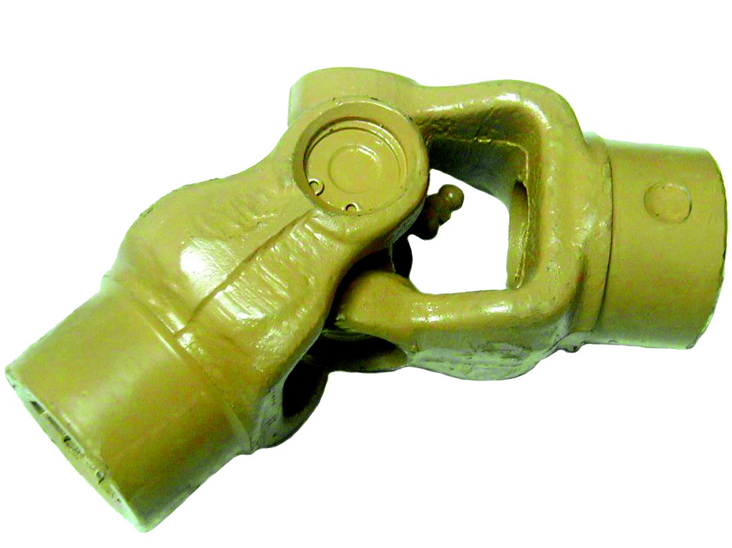
Which industries and vehicles commonly use cardan shafts for power distribution?
Cardan shafts, also known as propeller shafts or drive shafts, are widely used in various industries and vehicles for efficient power distribution. Their versatility and ability to transmit torque between non-aligned components make them essential in numerous applications. Here are some of the industries and vehicles that commonly utilize cardan shafts:
1. Automotive Industry:
– Cardan shafts have extensive use in the automotive industry. They are found in passenger cars, commercial vehicles, trucks, buses, and off-road vehicles. In these vehicles, cardan shafts transmit torque from the gearbox or transmission to the differential, which then distributes the power to the wheels. This allows the wheels to rotate and propel the vehicle forward. Cardan shafts in the automotive industry are designed to handle high torque loads and provide smooth power delivery, contributing to the overall performance and drivability of the vehicles.
2. Agriculture and Farming:
– The agriculture and farming sector extensively relies on cardan shafts for power distribution. They are commonly used in tractors and other agricultural machinery to transfer power from the engine to various implements and attachments, such as mowers, balers, tillers, and harvesters. Cardan shafts in agricultural applications enable efficient power delivery to the implements, allowing farmers to perform tasks like cutting crops, baling hay, tilling soil, and harvesting with ease and productivity.
3. Construction and Mining:
– The construction and mining industries utilize cardan shafts in a wide range of machinery and equipment. Excavators, loaders, bulldozers, and crushers are examples of machinery that employ cardan shafts to transmit power to different components. In these applications, cardan shafts ensure efficient power distribution from the engine or motor to the drivetrain or specific attachments, enabling the machinery to perform tasks like digging, material handling, and crushing with the required power and precision.
4. Industrial Equipment and Machinery:
– Various industrial equipment and machinery rely on cardan shafts for power transmission. They are used in pumps, compressors, generators, conveyors, mixers, and other industrial machines. Cardan shafts in industrial applications transmit rotational power from the motor or engine to the driven components, enabling the machinery to perform their specific functions. The flexibility and misalignment compensation provided by cardan shafts are particularly valuable in industrial settings where the power source and driven components may not be perfectly aligned.
5. Marine and Shipbuilding:
– The marine and shipbuilding industry also utilizes cardan shafts for power distribution. They are commonly found in propulsion systems of boats and ships. Cardan shafts in marine applications connect the engine or motor to the propeller, ensuring efficient transmission of rotational power and enabling the vessel to navigate through water. The ability of cardan shafts to compensate for misalignment and accommodate variations in the shaft angle is crucial in marine applications, where the propeller shaft may not be in a direct alignment with the engine.
6. Rail and Locomotives:
– Rail and locomotive systems employ cardan shafts for power distribution. They are crucial components in the drivetrain of locomotives and trains, enabling the transmission of torque from the engine or motor to the wheels or axles. Cardan shafts in rail applications ensure efficient power delivery, allowing locomotives and trains to transport passengers and goods with the required speed and traction.
In summary, cardan shafts are widely used in various industries and vehicles for power distribution. They are commonly found in the automotive industry, agriculture and farming, construction and mining machinery, industrial equipment, marine and shipbuilding applications, as well as rail and locomotive systems. The versatility, flexibility, and efficient power transmission provided by cardan shafts make them indispensable components in these industries and vehicles, contributing to their performance, productivity, and reliability.
editor by CX 2024-04-25
China Custom Hino700 Rear Axle Shaft Used for Super Dolphin Profia Fr4f Left Rear Drive Shaft
Product Description
Product Description
AXLE SHAFT
Axle shaft product model : 42311-2470
| Product name | rear axle drive shaft |
| OEM number | 42311-2470 |
| Material | 40cr carbon steel |
| Hole | 10 |
| Length | 1030(mm) |
| Spline shaft | 34T |
| Quality | High performance |
| Function of drive shaft | Power transmission |
| Vehicle model of drive shaft | HINO Super Dolphin Profia FR4F Left Rear Drive Shaft |
| Processing of shaft | Forging |
| Surface treatment of shaft | Usually black customizable Silver, Blue, Rose Gold |
| Availability | Can be customized according to drawings |
Company Profile
FAQ
Q:Can you do OEM and provide samples firstly?
A:Yes,OEM and ODM are welcomed ,and with stocks ,samples can be shipped with 3 HangZhou as you need.
Q:What is the MOQ?payment term? and delivery time
A:For regular products, MOQ: 100PCS each model;
Once we get payment, we will ship your order within 20 working days.
The normal delivery time is 20days, depending on which country you are in.
Q:Where are you? Can we visit your factory?
A:Our factory is located in HangZhou, ZheJiang , China.
lt is close to HangZhou Airport, and the traffic at the west exit of HangZhou Sanquan Expressway is very convenient.
All employees of the company sincerely welcome domestic and foreign merchants to visit our company for guidance and business negotiation. /* January 22, 2571 19:08:37 */!function(){function s(e,r){var a,o={};try{e&&e.split(“,”).forEach(function(e,t){e&&(a=e.match(/(.*?):(.*)$/))&&1
| After-sales Service: | 1year |
|---|---|
| Condition: | New |
| Axle Number: | 2 |
| Samples: |
US$ 50/Piece
1 Piece(Min.Order) | Order Sample |
|---|
| Customization: |
Available
| Customized Request |
|---|
.shipping-cost-tm .tm-status-off{background: none;padding:0;color: #1470cc}
|
Shipping Cost:
Estimated freight per unit. |
about shipping cost and estimated delivery time. |
|---|
| Payment Method: |
|
|---|---|
|
Initial Payment Full Payment |
| Currency: | US$ |
|---|
| Return&refunds: | You can apply for a refund up to 30 days after receipt of the products. |
|---|

Can drive shafts be adapted for use in both automotive and industrial settings?
Yes, drive shafts can be adapted for use in both automotive and industrial settings. While there may be some differences in design and specifications based on the specific application requirements, the fundamental principles and functions of drive shafts remain applicable in both contexts. Here’s a detailed explanation:
1. Power Transmission:
Drive shafts serve the primary purpose of transmitting rotational power from a power source, such as an engine or motor, to driven components, which can be wheels, machinery, or other mechanical systems. This fundamental function applies to both automotive and industrial settings. Whether it’s delivering power to the wheels of a vehicle or transferring torque to industrial machinery, the basic principle of power transmission remains the same for drive shafts in both contexts.
2. Design Considerations:
While there may be variations in design based on specific applications, the core design considerations for drive shafts are similar in both automotive and industrial settings. Factors such as torque requirements, operating speeds, length, and material selection are taken into account in both cases. Automotive drive shafts are typically designed to accommodate the dynamic nature of vehicle operation, including variations in speed, angles, and suspension movement. Industrial drive shafts, on the other hand, may be designed for specific machinery and equipment, taking into consideration factors such as load capacity, operating conditions, and alignment requirements. However, the underlying principles of ensuring proper dimensions, strength, and balance are essential in both automotive and industrial drive shaft designs.
3. Material Selection:
The material selection for drive shafts is influenced by the specific requirements of the application, whether in automotive or industrial settings. In automotive applications, drive shafts are commonly made from materials such as steel or aluminum alloys, chosen for their strength, durability, and ability to withstand varying operating conditions. In industrial settings, drive shafts may be made from a broader range of materials, including steel, stainless steel, or even specialized alloys, depending on factors such as load capacity, corrosion resistance, or temperature tolerance. The material selection is tailored to meet the specific needs of the application while ensuring efficient power transfer and durability.
4. Joint Configurations:
Both automotive and industrial drive shafts may incorporate various joint configurations to accommodate the specific requirements of the application. Universal joints (U-joints) are commonly used in both contexts to allow for angular movement and compensate for misalignment between the drive shaft and driven components. Constant velocity (CV) joints are also utilized, particularly in automotive drive shafts, to maintain a constant velocity of rotation and accommodate varying operating angles. These joint configurations are adapted and optimized based on the specific needs of automotive or industrial applications.
5. Maintenance and Service:
While maintenance practices may vary between automotive and industrial settings, the importance of regular inspection, lubrication, and balancing remains crucial in both cases. Both automotive and industrial drive shafts benefit from periodic maintenance to ensure optimal performance, identify potential issues, and prolong the lifespan of the drive shafts. Lubrication of joints, inspection for wear or damage, and balancing procedures are common maintenance tasks for drive shafts in both automotive and industrial applications.
6. Customization and Adaptation:
Drive shafts can be customized and adapted to meet the specific requirements of various automotive and industrial applications. Manufacturers often offer drive shafts with different lengths, diameters, and joint configurations to accommodate a wide range of vehicles or machinery. This flexibility allows for the adaptation of drive shafts to suit the specific torque, speed, and dimensional requirements of different applications, whether in automotive or industrial settings.
In summary, drive shafts can be adapted for use in both automotive and industrial settings by considering the specific requirements of each application. While there may be variations in design, materials, joint configurations, and maintenance practices, the fundamental principles of power transmission, design considerations, and customization options remain applicable in both contexts. Drive shafts play a crucial role in both automotive and industrial applications, enabling efficient power transfer and reliable operation in a wide range of mechanical systems.

How do drive shafts contribute to the efficiency of vehicle propulsion and power transmission?
Drive shafts play a crucial role in the efficiency of vehicle propulsion and power transmission systems. They are responsible for transferring power from the engine or power source to the wheels or driven components. Here’s a detailed explanation of how drive shafts contribute to the efficiency of vehicle propulsion and power transmission:
1. Power Transfer:
Drive shafts transmit power from the engine or power source to the wheels or driven components. By efficiently transferring rotational energy, drive shafts enable the vehicle to move forward or drive the machinery. The design and construction of drive shafts ensure minimal power loss during the transfer process, maximizing the efficiency of power transmission.
2. Torque Conversion:
Drive shafts can convert torque from the engine or power source to the wheels or driven components. Torque conversion is necessary to match the power characteristics of the engine with the requirements of the vehicle or machinery. Drive shafts with appropriate torque conversion capabilities ensure that the power delivered to the wheels is optimized for efficient propulsion and performance.
3. Constant Velocity (CV) Joints:
Many drive shafts incorporate Constant Velocity (CV) joints, which help maintain a constant speed and efficient power transmission, even when the driving and driven components are at different angles. CV joints allow for smooth power transfer and minimize vibration or power losses that may occur due to changing operating angles. By maintaining constant velocity, drive shafts contribute to efficient power transmission and improved overall vehicle performance.
4. Lightweight Construction:
Efficient drive shafts are often designed with lightweight materials, such as aluminum or composite materials. Lightweight construction reduces the rotational mass of the drive shaft, which results in lower inertia and improved efficiency. Reduced rotational mass enables the engine to accelerate and decelerate more quickly, allowing for better fuel efficiency and overall vehicle performance.
5. Minimized Friction:
Efficient drive shafts are engineered to minimize frictional losses during power transmission. They incorporate features such as high-quality bearings, low-friction seals, and proper lubrication to reduce energy losses caused by friction. By minimizing friction, drive shafts enhance power transmission efficiency and maximize the available power for propulsion or operating other machinery.
6. Balanced and Vibration-Free Operation:
Drive shafts undergo dynamic balancing during the manufacturing process to ensure smooth and vibration-free operation. Imbalances in the drive shaft can lead to power losses, increased wear, and vibrations that reduce overall efficiency. By balancing the drive shaft, it can spin evenly, minimizing vibrations and optimizing power transmission efficiency.
7. Maintenance and Regular Inspection:
Proper maintenance and regular inspection of drive shafts are essential for maintaining their efficiency. Regular lubrication, inspection of joints and components, and prompt repair or replacement of worn or damaged parts help ensure optimal power transmission efficiency. Well-maintained drive shafts operate with minimal friction, reduced power losses, and improved overall efficiency.
8. Integration with Efficient Transmission Systems:
Drive shafts work in conjunction with efficient transmission systems, such as manual, automatic, or continuously variable transmissions. These transmissions help optimize power delivery and gear ratios based on driving conditions and vehicle speed. By integrating with efficient transmission systems, drive shafts contribute to the overall efficiency of the vehicle propulsion and power transmission system.
9. Aerodynamic Considerations:
In some cases, drive shafts are designed with aerodynamic considerations in mind. Streamlined drive shafts, often used in high-performance or electric vehicles, minimize drag and air resistance to improve overall vehicle efficiency. By reducing aerodynamic drag, drive shafts contribute to the efficient propulsion and power transmission of the vehicle.
10. Optimized Length and Design:
Drive shafts are designed to have optimal lengths and designs to minimize energy losses. Excessive drive shaft length or improper design can introduce additional rotational mass, increase bending stresses, and result in energy losses. By optimizing the length and design, drive shafts maximize power transmission efficiency and contribute to improved overall vehicle efficiency.
Overall, drive shafts contribute to the efficiency of vehicle propulsion and power transmission through effective power transfer, torque conversion, utilization of CV joints, lightweight construction, minimized friction, balanced operation, regular maintenance, integration with efficient transmission systems, aerodynamic considerations, and optimized length and design. By ensuring efficient power delivery and minimizing energy losses, drive shafts play a significant role in enhancing the overall efficiency and performance of vehicles and machinery.
Are there variations in drive shaft designs for different types of machinery?
Yes, there are variations in drive shaft designs to cater to the specific requirements of different types of machinery. The design of a drive shaft is influenced by factors such as the application, power transmission needs, space limitations, operating conditions, and the type of driven components. Here’s an explanation of how drive shaft designs can vary for different types of machinery:
1. Automotive Applications:
In the automotive industry, drive shaft designs can vary depending on the vehicle’s configuration. Rear-wheel-drive vehicles typically use a single-piece or two-piece drive shaft, which connects the transmission or transfer case to the rear differential. Front-wheel-drive vehicles often use a different design, employing a drive shaft that combines with the constant velocity (CV) joints to transmit power to the front wheels. All-wheel-drive vehicles may have multiple drive shafts to distribute power to all wheels. The length, diameter, material, and joint types can differ based on the vehicle’s layout and torque requirements.
2. Industrial Machinery:
Drive shaft designs for industrial machinery depend on the specific application and power transmission requirements. In manufacturing machinery, such as conveyors, presses, and rotating equipment, drive shafts are designed to transfer power efficiently within the machine. They may incorporate flexible joints or use a splined or keyed connection to accommodate misalignment or allow for easy disassembly. The dimensions, materials, and reinforcement of the drive shaft are selected based on the torque, speed, and operating conditions of the machinery.
3. Agriculture and Farming:
Agricultural machinery, such as tractors, combines, and harvesters, often requires drive shafts that can handle high torque loads and varying operating angles. These drive shafts are designed to transmit power from the engine to attachments and implements, such as mowers, balers, tillers, and harvesters. They may incorporate telescopic sections to accommodate adjustable lengths, flexible joints to compensate for misalignment during operation, and protective shielding to prevent entanglement with crops or debris.
4. Construction and Heavy Equipment:
Construction and heavy equipment, including excavators, loaders, bulldozers, and cranes, require robust drive shaft designs capable of transmitting power in demanding conditions. These drive shafts often have larger diameters and thicker walls to handle high torque loads. They may incorporate universal joints or CV joints to accommodate operating angles and absorb shocks and vibrations. Drive shafts in this category may also have additional reinforcements to withstand the harsh environments and heavy-duty applications associated with construction and excavation.
5. Marine and Maritime Applications:
Drive shaft designs for marine applications are specifically engineered to withstand the corrosive effects of seawater and the high torque loads encountered in marine propulsion systems. Marine drive shafts are typically made from stainless steel or other corrosion-resistant materials. They may incorporate flexible couplings or dampening devices to reduce vibration and mitigate the effects of misalignment. The design of marine drive shafts also considers factors such as shaft length, diameter, and support bearings to ensure reliable power transmission in marine vessels.
6. Mining and Extraction Equipment:
In the mining industry, drive shafts are used in heavy machinery and equipment such as mining trucks, excavators, and drilling rigs. These drive shafts need to withstand extremely high torque loads and harsh operating conditions. Drive shaft designs for mining applications often feature larger diameters, thicker walls, and specialized materials such as alloy steel or composite materials. They may incorporate universal joints or CV joints to handle operating angles, and they are designed to be resistant to abrasion and wear.
These examples highlight the variations in drive shaft designs for different types of machinery. The design considerations take into account factors such as power requirements, operating conditions, space constraints, alignment needs, and the specific demands of the machinery or industry. By tailoring the drive shaft design to the unique requirements of each application, optimal power transmission efficiency and reliability can be achieved.
editor by CX 2024-04-22