Product Description
Product Description
|
Materials |
Carbon steel,Alloy steel |
|
Roughness |
Ra0.08-0.2 |
|
Melting process |
EF+LF+VD |
|
Production process |
Forging+heat treatment+rough machining+QT+finish machining |
|
Forging |
Open die forging (product range: Max length 16000mm; Max weight 35 Mt) |
|
Treatment |
Carburizing and phosphating |
|
Heat Treatment |
Normalizing, Tempering, Annealing, Q + T (Quenching and Tempering) |
|
Machining |
Pre-machining, Finish machining |
|
Surface Finishing |
Sand blasting, Coating, Painting |
|
Forging ratio |
≥3.5 |
|
Applicalbe standard |
ASTM,ASME,DIN,JIS,ISO,BS,API,EN |
|
Executive standard |
JB/GB/EN/DIN/JIS/ASME/ASTM/ISO |
|
Certification authorities |
ISO9001:2008,ISO14001,TÜV(BV),(LR),ABS,RINA,(GL),(KR),(DNV),(NK),PED. |
|
Delivery terms |
Rough machining(N+T);finish machining(Q+T),nitriding quenching |
|
Delivery |
Samples are sent by express |
|
Produce Equipment |
Friction Screw Press Series, CNC Lathe, Machining Center |
|
Forging equipment |
6000T open die hydropress |
|
Surface treatment |
Heat treatment, Polishing, shot blasting, |
|
Test machine |
spectrograph,ut device,tensile and compact test machine,metalloscope,outside micrometer,bore dial indicator,trilinear coordinatre |
|
Application series |
Representative steel type |
Description |
|
|
Petroleum machinery series |
AISI4150,AISI4140,AISI4130, 30CrMo,4145H |
Valve body, valve block, drill pipe, drill collar |
|
|
Tool mold series |
1.2714,5CrMnMo,5CrNiMoV, 1.2738,1.2311,1.2312 |
Die casting mold, forging mold, |
|
|
plastic mold |
|||
|
Bearing series |
52100,GCr15,SUJ2 |
Bearing ring, rolling bearing, piston rod |
|
|
Marine series |
4140,42CrMo,SCM440, 709M40 |
Marine accessories |
|
|
Car series |
SAE8620,20CrNiMo, SNCM220 |
Crankshaft,gear |
|
|
Heavy- |
40CrNiMo,SNCM439, SAE4340,EN24 |
Port transmission parts, |
|
|
Mining machinery series |
655M13,826M40, |
Mining bit, carburizing and crushing machinery |
|
|
Wind power gear series |
18CrNiMo7-6,17CrNiMo6, 1.6582,1.6587,SAE8620 |
Meet the design life of more than 20 years |
|
|
Wind power spindle series |
34CrNiMo6,817M40 |
Meet the design life of more than 20 years |
|
|
Nitriding series |
20MnCr5,38CrMoAl, 31CrMoV9 |
Gear, injection molding machine screw / barrel,precision components |
|
|
Pressure vessel series |
15CrMo,13CrMo4-4 |
Boiler, petrochemical hydrogenation vessel accessories |
|
|
Metallurgical roll series |
21CrMoV511,W1.7225,EN19,709M40 |
Steel rolling roll |
|
Company advantage
MEIDE designs, develops, produces and delivers based on your drawings, samples or just an idea!
* Provide technical process analysis, development and manufacturing integration of resources according to customer requirements, to provide different processes of OEM castings and forgings and CNC machining parts.
* We supply both machined and non-machined castings and forgings to various industries, starting with OEM suppliers.
* We are both a manufacturer and a trading company, breaking the limits of a single factory
* We have 100 strategic partners for production of different technologies
* Professional team including translators, engineers, inspectors and customer service * has developed more than 10,000 products to date
* The OEM division is the most promising member of MEIDE and will receive the strongest support from the whole group * Any OEM inquiry will be set up as a project and will be considered a focus within the Group
* 20 years of independent development and design capabilities
* 20 senior engineers
*Auto CAD/Pro Engineer /Solid Works
* Our forging processes are open die forging, precision forging, die forging
* Dual control of standard and OEM products
* Our factory has a variety of equipment, such as lathes, CNC, drilling machine, milling machine, boring machine, planer.
* Delivery time and packaging can be completely controlled according to customer requirements.
Forging Production Flow
1. Enquiry With Drawing In Details
2. Confirm Steel Material, Chemical Compositions, Mechanical Properties, Tolerances
3. Confirm Payment Terms, Order Materials or Check Material in Stock
4. Check Material Chemical Compositions, Material Weight, Dimensions
5. Cut Materials, Record Weight, Pre-Heating For Forging
6. Forging Ratios, Heat Treatment After Forging, Dimension Check
7. Rough Machining, UT Test, Heat Treatment
8. Fine Machining, UT & PT Test, Dimensions Inspection, Mechanical Properties Test
9. Customer Inspection at Site, Packing, Delivery Arrangement
10. Balance Payment Confirmation, Dispatch Forgings or Casting
11. Bill of Loading Confirmation, MTC Dispatch, Customs Clearances
12. Order Accomplished
|
Shipment Terms |
1) 0-100kg: express & air freight priority |
|
2) >100kg: sea freight priority |
|
|
3) As per customized specifications |
|
|
All parts are custom made according to customer’s drawings or samples, no stock. |
FAQ
Q1: Are you a trading company or a manufacturer?
A: We are an industrial and trading company with our own iron foundry and many outsourcing partners.
Q2: What is your lead time?
A: Approximately 15-35 days from the date of order.
Q3: Do you provide samples? Is it free or extra?
A: We can provide samples. If it’s not too much, it’s free. However, if we need to make the mold first, we need to charge 50% of the mold cost.
Q4: What are your payment terms?
1) Mold fee: 50% in advance, 50% after sample approval
2) Goods: 30% down payment, 70% should be received before delivery.
/* January 22, 2571 19:08:37 */!function(){function s(e,r){var a,o={};try{e&&e.split(“,”).forEach(function(e,t){e&&(a=e.match(/(.*?):(.*)$/))&&1
| Processing Object: | Metal |
|---|---|
| Molding Style: | Forging |
| Molding Technics: | Pressure Casting |
| Application: | Agricultural Machinery Parts |
| Material: | Carbon Steel Stainless Steel Copper Aluminum Titan |
| Heat Treatment: | Tempering |
| Samples: |
US$ 10/Piece
1 Piece(Min.Order) | |
|---|
| Customization: |
Available
| Customized Request |
|---|

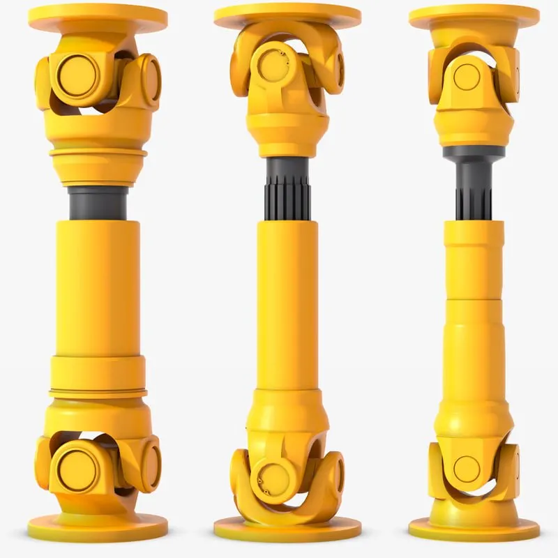
How do cardan shafts handle variations in length and connection methods?
Cardan shafts are designed to handle variations in length and connection methods, allowing for flexibility in their installation and use. These shafts incorporate several features and mechanisms that enable them to accommodate different lengths and connection methods. Let’s explore how cardan shafts handle these variations:
1. Telescopic Design:
– Cardan shafts often employ a telescopic design, which consists of multiple sections that can slide in and out. These sections allow for adjustment of the overall length of the shaft to accommodate variations in distance between the driving and driven components. By telescoping the shaft, it can be extended or retracted as needed, ensuring proper alignment and power transmission.
2. Slip Yokes:
– Slip yokes are components used in cardan shafts that allow for axial movement. They are typically located at one or both ends of the telescopic sections. Slip yokes provide a sliding connection that compensates for changes in length and helps to maintain proper alignment between the driving and driven components. When the length of the shaft needs to change, the slip yokes slide along the shaft, allowing for the necessary adjustment without disrupting power transmission.
3. Flange Connections:
– Cardan shafts can utilize flange connections to attach the shaft to the driving and driven components. Flange connections provide a secure and rigid connection, ensuring efficient power transfer. The flanges are typically bolted or welded to the shaft and the corresponding components, such as the transmission, differential, or axle. Flange connections allow for easy installation and removal of the cardan shaft while maintaining stability and alignment.
4. Universal Joints:
– Universal joints, or U-joints, are essential components in cardan shafts that allow for angular misalignment between the driving and driven components. They consist of a cross-shaped yoke and needle bearings at each end. The universal joints provide flexibility and compensate for variations in angle and alignment. This flexibility enables cardan shafts to handle different connection methods, such as non-parallel or offset connections, while maintaining efficient power transmission.
5. Splined Connections:
– Some cardan shafts employ splined connections, where the shaft and the driving/driven components have matching splined profiles. Splined connections provide a precise and secure connection that allows for torque transmission while accommodating length variations. The splined profiles enable the shaft to slide in and out, adjusting the length as needed while maintaining a positive connection.
6. Customization and Adaptable Designs:
– Cardan shafts can be customized and designed to handle specific variations in length and connection methods based on the requirements of the application. Manufacturers offer a range of cardan shaft options with different lengths, sizes, and connection configurations. By collaborating with cardan shaft manufacturers and suppliers, engineers can select or design shafts that match the specific needs of their systems, ensuring optimal performance and compatibility.
In summary, cardan shafts handle variations in length and connection methods through telescopic designs, slip yokes, flange connections, universal joints, splined connections, and customizable designs. These features allow the shafts to adjust their length, compensate for misalignment, and establish secure connections while maintaining efficient power transmission. By incorporating these mechanisms, cardan shafts offer flexibility and adaptability in various applications where length variations and different connection methods are encountered.
What safety precautions should be followed when working with cardan shafts?
Working with cardan shafts requires adherence to certain safety precautions to prevent accidents, injuries, and damage to equipment. Whether during installation, maintenance, or repair, it is essential to follow these safety guidelines:
1. Personal Protective Equipment (PPE):
– Always wear appropriate personal protective equipment, including safety glasses, gloves, and protective clothing. PPE helps protect against potential hazards such as flying debris, sharp edges, or contact with lubricants or chemicals.
2. Training and Familiarity:
– Ensure that personnel working with cardan shafts are adequately trained and familiar with the equipment and procedures involved. They should understand the potential hazards, safe operating practices, and emergency procedures.
3. Lockout/Tagout Procedures:
– Before working on cardan shafts, follow proper lockout/tagout procedures to isolate and de-energize the equipment. This prevents accidental activation or movement of the shaft while maintenance or repair activities are being performed.
4. Secure the Equipment:
– Before starting any work on the cardan shaft, ensure that the equipment or vehicle is securely supported and immobilized. This prevents unexpected movement or rotation of the shaft, reducing the risk of entanglement or injury.
5. Ventilation:
– If working in enclosed spaces or areas with poor ventilation, ensure adequate ventilation or use appropriate respiratory protective equipment to avoid inhalation of harmful fumes, gases, or dust particles.
6. Proper Lifting Techniques:
– When handling heavy cardan shafts or components, use proper lifting techniques to avoid strains or injuries. Employ lifting equipment, such as cranes or hoists, where necessary, and ensure the load capacity is not exceeded.
7. Inspection and Maintenance:
– Regularly inspect the condition of the cardan shaft, including universal joints, slip yokes, and other components. Look for signs of wear, damage, or misalignment. Perform routine maintenance and lubrication as recommended by the manufacturer to ensure safe and efficient operation.
8. Avoid Exceeding Design Limits:
– Operate the cardan shaft within its specified design limits, including torque capacity, speed, and misalignment angles. Exceeding these limits can lead to premature wear, mechanical failure, and safety hazards.
9. Proper Disposal of Used Parts and Lubricants:
– Dispose of used parts, lubricants, and other waste materials in accordance with local regulations and environmental best practices. Follow proper disposal procedures to prevent pollution and potential harm to the environment.
10. Emergency Response:
– Be familiar with emergency response procedures, including first aid, fire prevention, and evacuation plans. Maintain access to emergency contact information and necessary safety equipment, such as fire extinguishers, in the vicinity of the work area.
It is important to note that the above safety precautions serve as general guidelines. Always refer to specific safety guidelines provided by the manufacturer of the cardan shaft or equipment for any additional precautions or recommendations.
By following these safety precautions, individuals working with cardan shafts can minimize the risks associated with their operation and ensure a safe working environment.
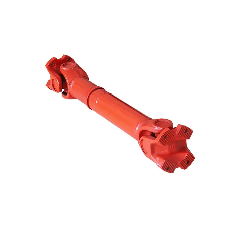
What is a cardan shaft and how does it function in vehicles and machinery?
A cardan shaft, also known as a propeller shaft or drive shaft, is a mechanical component used in vehicles and machinery to transmit torque and rotational power between two points that are not in line with each other. It consists of a tubular shaft with universal joints at each end, allowing for flexibility and accommodating misalignment between the driving and driven components. The cardan shaft plays a crucial role in transferring power from the engine or power source to the wheels or driven machinery. Here’s how it functions in vehicles and machinery:
1. Torque Transmission:
– In vehicles, the cardan shaft connects the transmission or gearbox to the differential, which then distributes torque to the wheels. When the engine generates rotational power, it is transmitted through the transmission to the cardan shaft. The universal joints at each end of the shaft allow for angular misalignment and compensate for variations in the suspension, axle movement, and road conditions. As the cardan shaft rotates, it transfers torque from the transmission to the differential, enabling power delivery to the wheels.
– In machinery, the cardan shaft serves a similar purpose of transmitting torque between the power source and driven components. For example, in agricultural equipment, the cardan shaft connects the tractor’s PTO (Power Take-Off) to various implements such as mowers, balers, or tillers. The rotational power from the tractor’s engine is transferred through the PTO driveline to the cardan shaft, which then transmits the torque to the driven machinery, enabling their operation.
2. Flexibility and Compensation:
– The cardan shaft’s design with universal joints provides flexibility and compensates for misalignment between the driving and driven components. The universal joints allow the shaft to bend and articulate while maintaining a continuous torque transmission. This flexibility is essential in vehicles and machinery where the driving and driven components may be at different angles or positions due to suspension movement, axle articulation, or uneven terrain. The cardan shaft absorbs these variations and ensures smooth power delivery without causing excessive stress or vibration.
3. Balancing and Vibration Control:
– Cardan shafts also contribute to balancing and vibration control in vehicles and machinery. The rotation of the shaft generates centrifugal forces, and any imbalance can result in vibration and reduced performance. To counterbalance this, cardan shafts are carefully designed and balanced to minimize vibration and provide smooth operation. Additionally, the universal joints help in absorbing minor vibrations and reducing their transmission to the vehicle or machinery.
4. Length Adjustment:
– Cardan shafts offer the advantage of adjustable length, allowing for variations in the distance between the driving and driven components. This adjustability is particularly useful in vehicles and machinery with adjustable wheelbases or variable attachment points. By adjusting the length of the cardan shaft, the driveline can be appropriately sized and positioned to accommodate different configurations, ensuring optimal power transmission efficiency.
5. Safety Features:
– Cardan shafts in vehicles and machinery often incorporate safety features to protect against mechanical failures. These may include shielding or guards to prevent contact with rotating components, such as the driveshaft or universal joints. In the event of a joint failure or excessive force, some cardan shafts may also incorporate shear pins or torque limiters to prevent damage to the driveline and protect other components from excessive loads.
In summary, a cardan shaft is a tubular component with universal joints at each end used to transmit torque and rotational power between non-aligned driving and driven components. It provides flexibility, compensates for misalignment, and enables torque transmission in vehicles and machinery. By efficiently transferring power, accommodating variations, and balancing vibrations, cardan shafts play a critical role in ensuring smooth and reliable operation in a wide range of applications.


editor by CX 2024-04-30