Product Description
| Product Name | Cardan Shaft |
| Product Model | SWC-I75A-335+40 |
| Main Material | 35CrMo or 45# Steel |
| Nominal Torque | 500 N.M |
| Normal Length | 335 mm |
| Length Compensation | 40 mm |
/* January 22, 2571 19:08:37 */!function(){function s(e,r){var a,o={};try{e&&e.split(“,”).forEach(function(e,t){e&&(a=e.match(/(.*?):(.*)$/))&&1
| Standard Or Nonstandard: | Nonstandard |
|---|---|
| Shaft Hole: | 19-32 |
| Torque: | >80N.M |
| Samples: |
US$ 10/Piece
1 Piece(Min.Order) | Order Sample |
|---|
| Customization: |
Available
| Customized Request |
|---|
.shipping-cost-tm .tm-status-off{background: none;padding:0;color: #1470cc}
| Shipping Cost:
Estimated freight per unit. |
about shipping cost and estimated delivery time. |
|---|
| Payment Method: |
|
|---|---|
|
Initial Payment Full Payment |
| Currency: | US$ |
|---|
| Return&refunds: | You can apply for a refund up to 30 days after receipt of the products. |
|---|

How do cardan shafts handle variations in length and connection methods?
Cardan shafts are designed to handle variations in length and connection methods, allowing for flexibility in their installation and use. These shafts incorporate several features and mechanisms that enable them to accommodate different lengths and connection methods. Let’s explore how cardan shafts handle these variations:
1. Telescopic Design:
– Cardan shafts often employ a telescopic design, which consists of multiple sections that can slide in and out. These sections allow for adjustment of the overall length of the shaft to accommodate variations in distance between the driving and driven components. By telescoping the shaft, it can be extended or retracted as needed, ensuring proper alignment and power transmission.
2. Slip Yokes:
– Slip yokes are components used in cardan shafts that allow for axial movement. They are typically located at one or both ends of the telescopic sections. Slip yokes provide a sliding connection that compensates for changes in length and helps to maintain proper alignment between the driving and driven components. When the length of the shaft needs to change, the slip yokes slide along the shaft, allowing for the necessary adjustment without disrupting power transmission.
3. Flange Connections:
– Cardan shafts can utilize flange connections to attach the shaft to the driving and driven components. Flange connections provide a secure and rigid connection, ensuring efficient power transfer. The flanges are typically bolted or welded to the shaft and the corresponding components, such as the transmission, differential, or axle. Flange connections allow for easy installation and removal of the cardan shaft while maintaining stability and alignment.
4. Universal Joints:
– Universal joints, or U-joints, are essential components in cardan shafts that allow for angular misalignment between the driving and driven components. They consist of a cross-shaped yoke and needle bearings at each end. The universal joints provide flexibility and compensate for variations in angle and alignment. This flexibility enables cardan shafts to handle different connection methods, such as non-parallel or offset connections, while maintaining efficient power transmission.
5. Splined Connections:
– Some cardan shafts employ splined connections, where the shaft and the driving/driven components have matching splined profiles. Splined connections provide a precise and secure connection that allows for torque transmission while accommodating length variations. The splined profiles enable the shaft to slide in and out, adjusting the length as needed while maintaining a positive connection.
6. Customization and Adaptable Designs:
– Cardan shafts can be customized and designed to handle specific variations in length and connection methods based on the requirements of the application. Manufacturers offer a range of cardan shaft options with different lengths, sizes, and connection configurations. By collaborating with cardan shaft manufacturers and suppliers, engineers can select or design shafts that match the specific needs of their systems, ensuring optimal performance and compatibility.
In summary, cardan shafts handle variations in length and connection methods through telescopic designs, slip yokes, flange connections, universal joints, splined connections, and customizable designs. These features allow the shafts to adjust their length, compensate for misalignment, and establish secure connections while maintaining efficient power transmission. By incorporating these mechanisms, cardan shafts offer flexibility and adaptability in various applications where length variations and different connection methods are encountered.
How do cardan shafts enhance the performance of trucks and heavy-duty vehicles?
Cardan shafts play a significant role in enhancing the performance of trucks and heavy-duty vehicles. These vehicles often operate under demanding conditions, requiring robust and efficient power transmission systems. Here’s how cardan shafts contribute to the performance of trucks and heavy-duty vehicles:
1. Torque Transmission:
– Cardan shafts enable the efficient transmission of torque from the engine or transmission to the drivetrain and wheels of trucks and heavy-duty vehicles. They can handle high torque loads, ensuring that power is effectively transferred to propel the vehicle forward. This efficient torque transmission enhances acceleration, towing capacity, and overall performance.
2. Power Distribution:
– Trucks and heavy-duty vehicles often have multiple axles or wheels. Cardan shafts distribute power to each axle or wheel, ensuring balanced power delivery. This helps improve traction, stability, and control, especially when carrying heavy loads or operating on challenging terrains. By optimizing power distribution, cardan shafts enhance the vehicle’s performance and handling characteristics.
3. Flexibility and Misalignment Compensation:
– Cardan shafts are designed to accommodate misalignment between the engine, transmission, and drivetrain components. They can handle angular misalignment, parallel offset, and axial displacement. This flexibility allows for smooth power transmission even when the components are not perfectly aligned, reducing stress on the drivetrain and improving performance. It also helps absorb vibrations and shocks, enhancing driver comfort and reducing wear on other vehicle components.
4. Durability and Reliability:
– Heavy-duty vehicles operate in rugged and demanding conditions, such as construction sites, mining operations, or long-haul transportation. Cardan shafts are built to withstand these harsh environments, providing durability and reliability. They are designed using robust materials and undergo rigorous testing to ensure they can handle the high torque, heavy loads, and continuous operation that trucks and heavy-duty vehicles require. This reliability minimizes downtime and maintenance, improving overall vehicle performance.
5. Powertrain Efficiency:
– Cardan shafts help optimize powertrain efficiency in trucks and heavy-duty vehicles. By efficiently transmitting torque and minimizing power loss during power transfer, they contribute to improved fuel economy and reduced energy consumption. This increased efficiency translates to cost savings and reduced environmental impact.
6. Weight Reduction:
– Cardan shafts offer weight reduction benefits for trucks and heavy-duty vehicles. The use of lightweight materials and optimized designs helps reduce the overall weight of the propulsion system. Reduced weight improves fuel efficiency, increases payload capacity, and enhances vehicle maneuverability. Cardan shafts’ compactness and space-saving design also allow for more efficient packaging of the drivetrain components.
7. Adaptability to Various Configurations:
– Trucks and heavy-duty vehicles come in different configurations, such as rear-wheel drive (RWD), front-wheel drive (FWD), or all-wheel drive (AWD). Cardan shafts can be tailored to suit these various drivetrain setups, providing the necessary torque transmission and power distribution for each configuration. This adaptability allows manufacturers to optimize vehicle performance based on specific application requirements.
Overall, cardan shafts enhance the performance of trucks and heavy-duty vehicles by enabling efficient torque transmission, balancing power distribution, compensating for misalignment, providing durability and reliability, optimizing powertrain efficiency, reducing weight, and adapting to various drivetrain configurations. Their role in improving acceleration, towing capacity, traction, and fuel economy contributes to the overall performance and success of these vehicles in demanding environments.

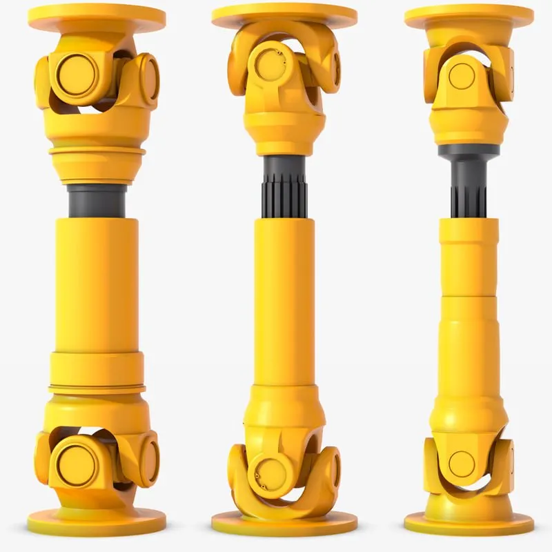
Can you explain the components and structure of a cardan shaft system?
A cardan shaft system, also known as a propeller shaft or drive shaft, consists of several components that work together to transmit torque and rotational power between non-aligned components. The structure of a cardan shaft system typically includes the following components:
1. Shaft Tubes:
– The shaft tubes are the main structural elements of a cardan shaft system. They are cylindrical tubes made of durable and high-strength materials such as steel or aluminum alloy. The shaft tubes provide the backbone of the system and are responsible for transmitting torque and rotational power. They are designed to withstand high loads and torsional forces without deformation or failure.
2. Universal Joints:
– Universal joints, also known as U-joints or Cardan joints, are crucial components of a cardan shaft system. They are used to connect and articulate the shaft tubes, allowing for angular misalignment between the driving and driven components. Universal joints consist of a cross-shaped yoke with needle bearings at each end. The yoke connects the shaft tubes, while the needle bearings enable the rotational motion and flexibility required for misalignment compensation. Universal joints allow the cardan shaft system to transmit torque even when the driving and driven components are not perfectly aligned.
3. Slip Yokes:
– Slip yokes are components used in cardan shaft systems that can accommodate axial misalignment. They are typically located at one or both ends of the shaft tubes and provide a sliding connection between the shaft and the driving or driven component. Slip yokes allow the shaft to adjust its length and compensate for changes in the distance between the components. This feature is particularly useful in applications where the distance between the driving and driven components can vary, such as vehicles with adjustable wheelbases or machinery with variable attachment points.
4. Flanges and Yokes:
– Flanges and yokes are used to connect the cardan shaft system to the driving and driven components. Flanges are typically bolted or welded to the ends of the shaft tubes and provide a secure connection point. They have a flange face with bolt holes that align with the corresponding flange on the driving or driven component. Yokes, on the other hand, are cross-shaped components that connect the universal joints to the flanges. They have holes or grooves that accommodate the needle bearings of the universal joints, allowing for rotational motion and torque transfer.
5. Balancing Weights:
– Balancing weights are used to balance the cardan shaft system and minimize vibrations. As the shaft rotates, imbalances in the mass distribution can lead to vibrations, noise, and reduced performance. Balancing weights are strategically placed along the shaft tubes to counterbalance these imbalances. They redistribute the mass, ensuring that the rotational components of the cardan shaft system are properly balanced. Proper balancing improves stability, reduces wear on bearings and other components, and enhances the overall performance and lifespan of the shaft system.
6. Safety Features:
– Some cardan shaft systems incorporate safety features to protect against mechanical failures. For example, protective guards or shielding may be installed to prevent contact with rotating components, reducing the risk of accidents or injuries. In applications where excessive forces or torques can occur, cardan shaft systems may include safety mechanisms such as shear pins or torque limiters. These features are designed to protect the shaft and other components from damage by shearing or disengaging in case of overload or excessive torque.
In summary, a cardan shaft system consists of shaft tubes, universal joints, slip yokes, flanges, and yokes, as well as balancing weights and safety features. These components work together to transmit torque and rotational power between non-aligned components, allowing for angular and axial misalignment compensation. The structure and components of a cardan shaft system are carefully designed to ensure efficient power transmission, flexibility, durability, and safety in various applications.


editor by CX 2024-03-26
Cardan China broken pto shaft Shafts for Industrial Equipments Rubber Machinery Rolling Mills with ce certificate top quality low price
We – EPG Team the biggest agricultural gearbox and pto manufacturing unit in China with 5 various branches. For more details: Cellular/whatsapp/telegram/Kakao us at: 0086-13083988828

pto yoke areas Adhering mahindra tractor pto shaft to pto shaft horsepower ranking “Survival little generate shaft by 540 pto adapter Top quality, pto shaft shear pin Development pto shaft basic safety guard by shaft generators / pto-pti-pth Engineering fn2 driveshaft & truck pto shaft Credit score”, The company will consistently boost item functionality to satisfy the rising consumer demands in the demanding fashion of function. It is our aim to provide a vast selection of high quality goods at affordable charges, give the greatest service for consumers satisfied and contribute to our ongoing enhancement. SWC Sequence-Medium-Obligation Styles Cardan shaft
Types
Data and Measurements of SWC Sequence Universal Joint Couplings
| Sort | Layout Information Product |
SWC160 | SWC180 | SWC200 | SWC225 | SWC250 | SWC265 | SWC285 | SWC315 | SWC350 | SWC390 | SWC440 | SWC490 | SWC550 | SWC620 |
| A | L | 740 | 800 | 900 | one thousand | 1060 | 1120 | 1270 | 1390 | 1520 | 1530 | 1690 | 1850 | 2060 | 2280 |
| LV | 100 | a hundred | a hundred and twenty | 140 | one hundred forty | one hundred forty | a hundred and forty | a hundred and forty | 150 | 170 | one hundred ninety | one hundred ninety | 240 | 250 | |
| M(kg) | 65 | 83 | one hundred fifteen | 152 | 219 | 260 | 311 | 432 | 610 | 804 | 1122 | 1468 | 2154 | 2830 | |
| B | L | 480 | 530 | 590 | 640 | 730 | 790 | 840 | 930 | 100 | 1571 | 1130 | 1340 | 1400 | 1520 |
| M(kg) | forty four | 60 | 85 | 110 | a hundred and sixty | 180 | 226 | 320 | 440 | 590 | 820 | 1090 | 1560 | 2100 | |
| C | L | 380 | 420 | 480 | 500 | 560 | 600 | 640 | 720 | 782 | 860 | 1040 | 1080 | 1220 | 1360 |
| M(kg) | 35 | 48 | sixty six | ninety | a hundred thirty | 160 | 189 | 270 | 355 | 510 | 780 | 970 | 1330 | 1865 | |
| D | L | 520 | 580 | 620 | 690 | 760 | 810 | 860 | 970 | 1030 | 1120 | 1230 | 1360 | 1550 | 1720 |
| M(kg) | forty eight | 65 | ninety | 120 | 173 | 220 | 250 | 355 | 485 | 665 | 920 | 1240 | 1765 | 2390 | |
| E | L | 800 | 850 | 940 | 1050 | 1120 | 1180 | 1320 | 1440 | 1550 | 1710 | 1880 | 2050 | 2310 | 2540 |
| LV | 100 | a hundred | a hundred and twenty | a hundred and forty | a hundred and forty | one hundred forty | one hundred forty | a hundred and forty | 150 | one hundred seventy | one hundred ninety | 190 | 240 | 250 | |
| M(kg) | 70 | 92 | 126 | 165 | 238 | 280 | 340 | 472 | 660 | 886 | 1230 | 1625 | 2368 | 3135 | |
| Tn(kN·m) | sixteen | 22.4 | 31.five | 40 | 63 | 80 | ninety | 125 | one hundred eighty | 250 | 355 | five hundred | 710 | one thousand | |
| TF(kN·m) | 8 | eleven.2 | sixteen | 20 | 31.5 | 40 | 45 | sixty three | ninety | a hundred twenty five | one hundred eighty | 250 | 355 | 500 | |
| Β(°) | fifteen | 15 | 15 | fifteen | 15 | fifteen | fifteen | 15 | 15 | 15 | 15 | fifteen | 15 | fifteen | |
| D | 160 | a hundred and eighty | 200 | 225 | 250 | 265 | 285 | 315 | 350 | 390 | 440 | 490 | 550 | 620 | |
| Df | a hundred and sixty | 180 | 200 | 225 | 250 | 265 | 285 | 315 | 350 | 3690 | 440 | 490 | 550 | 620 | |
| D1 | 137 | 155 | 170 | 196 | 218 | 233 | 245 | 280 | 310 | 345 | 390 | 435 | 492 | 555 | |
| D2(H9) | a hundred | 105 | one hundred twenty | one hundred thirty five | 150 | 160 | 170 | 185 | 210 | 235 | 255 | 275 | 320 | 380 | |
| D3 | 108 | 114 | a hundred and forty | 159 | 168 | a hundred and eighty | 194 | 219 | 245 | 273 | 299 | 325 | 402 | 426 | |
| Lm | ninety five | one hundred and five | 110 | one hundred twenty five | 140 | one hundred fifty | a hundred and sixty | one hundred eighty | 195 | 215 | 260 | 270 | 305 | 340 | |
| K | 16 | seventeen | eighteen | 20 | 25 | twenty five | 27 | 32 | 35 | forty | forty two | 47 | fifty | fifty five | |
| T | four | five | 5 | five | six | 6 | seven | eight | 8 | eight | ten | 12 | 12 | twelve | |
| N | eight | eight | 8 | eight | 8 | eight | 8 | ten | 10 | ten | 16 | 16 | sixteen | sixteen | |
| D | 15 | 17 | 17 | 17 | 19 | 19 | 21 | 23 | 23 | twenty five | 28 | 31 | 31 | 38 | |
| B | twenty | 24 | 32 | 32 | 40 | forty | forty | forty | 50 | 70 | 80 | 90 | 100 | a hundred | |
| G | 6. | 7. | nine. | 9. | 12.five | twelve.five | twelve.5 | fifteen. | sixteen. | 18. | 20. | 22.five | 22.5 | 25 | |
| MI(Kg) | two.fifty seven | three | three.85 | three.eighty five | five.17 | 6 | six.75 | eight.twenty five | ten.six | thirteen | eighteen.fifty | 23.seventy five | 29.twelve | 38.08 | |
| Measurement | M14 | M16 | M16 | M16 | M18 | M18 | M20 | M22 | M22 | M24 | M27 | M30 | M30 | M36 | |
| Tightening torque(Nm) | one hundred eighty | 270 | 270 | 270 | 372 | 372 | 526 | 710 | 710 | 906 | 1340 | 1820 | 1820 | 3170 |
one. Notations:
L=StHangZhourd length, or compressed length for designs with length compensation
LV=Length compensation
M=Weight
Tn=Nominal torque(Yield torque 50% over Tn)
TF=Fatigue torque, I. E. Permissible torque as determined according to the fatigue strength
Under reversing loads
β=Maximum deflection angle
MI=weight per 100mm tube
2. Millimeters are used as measurement units except where noted
3. Please consult us for customizations regarding length, length compensation and
Flange connections.
(DIN or SAT etc. )
