Product Description
You can kindly find the specification details below:
HangZhou Mastery Machinery Technology Co., LTD helps manufacturers and brands fulfill their machinery parts by precision manufacturing. High precision machinery products like the shaft, worm screw, bushing, couplings, joints……Our products are used widely in electronic motors, the main shaft of the engine, the transmission shaft in the gearbox, couplers, printers, pumps, drones, and so on. They cater to different industries, including automotive, industrial, power tools, garden tools, healthcare, smart home, etc.
Mastery caters to the industrial industry by offering high-level Cardan shafts, pump shafts, and a bushing that come in different sizes ranging from diameter 3mm-50mm. Our products are specifically formulated for transmissions, robots, gearboxes, industrial fans, and drones, etc.
Mastery factory currently has more than 100 main production equipment such as CNC lathe, CNC machining center, CAM Automatic Lathe, grinding machine, hobbing machine, etc. The production capacity can be up to 5-micron mechanical tolerance accuracy, automatic wiring machine processing range covering 3mm-50mm diameter bar.
Key Specifications:
| Name | Shaft/Motor Shaft/Drive Shaft/Gear Shaft/Pump Shaft/Worm Screw/Worm Gear/Bushing/Ring/Joint/Pin |
| Material | 40Cr/35C/GB45/70Cr/40CrMo |
| Process | Machining/Lathing/Milling/Drilling/Grinding/Polishing |
| Size | 2-400mm(Customized) |
| Diameter | φ12(Customized) |
| Diameter Tolerance | 0.008mm |
| Roundness | 0.01mm |
| Roughness | Ra0.4 |
| Straightness | 0.01mm |
| Hardness | Customized |
| Length | 32mm(Customized) |
| Heat Treatment | Customized |
| Surface treatment | Coating/Ni plating/Zn plating/QPQ/Carbonization/Quenching/Black Treatment/Steaming Treatment/Nitrocarburizing/Carbonitriding |
Quality Management:
- Raw Material Quality Control: Chemical Composition Analysis, Mechanical Performance Test, ROHS, and Mechanical Dimension Check
- Production Process Quality Control: Full-size inspection for the 1st part, Critical size process inspection, SPC process monitoring
- Lab ability: CMM, OGP, XRF, Roughness meter, Profiler, Automatic optical inspector
- Quality system: ISO9001, IATF 16949, ISO14001
- Eco-Friendly: ROHS, Reach.
Packaging and Shipping:
Throughout the entire process of our supply chain management, consistent on-time delivery is vital and very important for the success of our business.
Mastery utilizes several different shipping methods that are detailed below:
For Samples/Small Q’ty: By Express Services or Air Fright.
For Formal Order: By Sea or by air according to your requirement.
Mastery Services:
- One-Stop solution from idea to product/ODM&OEM acceptable
- Individual research and sourcing/purchasing tasks
- Individual supplier management/development, on-site quality check projects
- Muti-varieties/small batch/customization/trial orders are acceptable
- Flexibility on quantity/Quick samples
- Forecast and raw material preparation in advance are negotiable
- Quick quotes and quick responses
General Parameters:
If you are looking for a reliable machinery product partner, you can rely on Mastery. Work with us and let us help you grow your business using our customizable and affordable products. /* January 22, 2571 19:08:37 */!function(){function s(e,r){var a,o={};try{e&&e.split(“,”).forEach(function(e,t){e&&(a=e.match(/(.*?):(.*)$/))&&1
| Material: | Carbon Steel |
|---|---|
| Load: | Drive Shaft |
| Stiffness & Flexibility: | Stiffness / Rigid Axle |
| Journal Diameter Dimensional Accuracy: | IT6-IT9 |
| Axis Shape: | Straight Shaft |
| Shaft Shape: | Real Axis |
| Customization: |
Available
| Customized Request |
|---|

Are there any limitations or disadvantages associated with drive shafts?
While drive shafts are widely used and offer several advantages, they also have certain limitations and disadvantages that should be considered. Here’s a detailed explanation of the limitations and disadvantages associated with drive shafts:
1. Length and Misalignment Constraints:
Drive shafts have a maximum practical length due to factors such as material strength, weight considerations, and the need to maintain rigidity and minimize vibrations. Longer drive shafts can be prone to increased bending and torsional deflection, leading to reduced efficiency and potential driveline vibrations. Additionally, drive shafts require proper alignment between the driving and driven components. Misalignment can cause increased wear, vibrations, and premature failure of the drive shaft or its associated components.
2. Limited Operating Angles:
Drive shafts, especially those using U-joints, have limitations on operating angles. U-joints are typically designed to operate within specific angular ranges, and operating beyond these limits can result in reduced efficiency, increased vibrations, and accelerated wear. In applications requiring large operating angles, constant velocity (CV) joints are often used to maintain a constant speed and accommodate greater angles. However, CV joints may introduce higher complexity and cost compared to U-joints.
3. Maintenance Requirements:
Drive shafts require regular maintenance to ensure optimal performance and reliability. This includes periodic inspection, lubrication of joints, and balancing if necessary. Failure to perform routine maintenance can lead to increased wear, vibrations, and potential driveline issues. Maintenance requirements should be considered in terms of time and resources when using drive shafts in various applications.
4. Noise and Vibration:
Drive shafts can generate noise and vibrations, especially at high speeds or when operating at certain resonant frequencies. Imbalances, misalignment, worn joints, or other factors can contribute to increased noise and vibrations. These vibrations may affect the comfort of vehicle occupants, contribute to component fatigue, and require additional measures such as dampers or vibration isolation systems to mitigate their effects.
5. Weight and Space Constraints:
Drive shafts add weight to the overall system, which can be a consideration in weight-sensitive applications, such as automotive or aerospace industries. Additionally, drive shafts require physical space for installation. In compact or tightly packaged equipment or vehicles, accommodating the necessary drive shaft length and clearances can be challenging, requiring careful design and integration considerations.
6. Cost Considerations:
Drive shafts, depending on their design, materials, and manufacturing processes, can involve significant costs. Customized or specialized drive shafts tailored to specific equipment requirements may incur higher expenses. Additionally, incorporating advanced joint configurations, such as CV joints, can add complexity and cost to the drive shaft system.
7. Inherent Power Loss:
Drive shafts transmit power from the driving source to the driven components, but they also introduce some inherent power loss due to friction, bending, and other factors. This power loss can reduce overall system efficiency, particularly in long drive shafts or applications with high torque requirements. It is important to consider power loss when determining the appropriate drive shaft design and specifications.
8. Limited Torque Capacity:
While drive shafts can handle a wide range of torque loads, there are limits to their torque capacity. Exceeding the maximum torque capacity of a drive shaft can lead to premature failure, resulting in downtime and potential damage to other driveline components. It is crucial to select a drive shaft with sufficient torque capacity for the intended application.
Despite these limitations and disadvantages, drive shafts remain a widely used and effective means of power transmission in various industries. Manufacturers continuously work to address these limitations through advancements in materials, design techniques, joint configurations, and balancing processes. By carefully considering the specific application requirements and potential drawbacks, engineers and designers can mitigate the limitations and maximize the benefits of drive shafts in their respective systems.

How do drive shafts contribute to the efficiency of vehicle propulsion and power transmission?
Drive shafts play a crucial role in the efficiency of vehicle propulsion and power transmission systems. They are responsible for transferring power from the engine or power source to the wheels or driven components. Here’s a detailed explanation of how drive shafts contribute to the efficiency of vehicle propulsion and power transmission:
1. Power Transfer:
Drive shafts transmit power from the engine or power source to the wheels or driven components. By efficiently transferring rotational energy, drive shafts enable the vehicle to move forward or drive the machinery. The design and construction of drive shafts ensure minimal power loss during the transfer process, maximizing the efficiency of power transmission.
2. Torque Conversion:
Drive shafts can convert torque from the engine or power source to the wheels or driven components. Torque conversion is necessary to match the power characteristics of the engine with the requirements of the vehicle or machinery. Drive shafts with appropriate torque conversion capabilities ensure that the power delivered to the wheels is optimized for efficient propulsion and performance.
3. Constant Velocity (CV) Joints:
Many drive shafts incorporate Constant Velocity (CV) joints, which help maintain a constant speed and efficient power transmission, even when the driving and driven components are at different angles. CV joints allow for smooth power transfer and minimize vibration or power losses that may occur due to changing operating angles. By maintaining constant velocity, drive shafts contribute to efficient power transmission and improved overall vehicle performance.
4. Lightweight Construction:
Efficient drive shafts are often designed with lightweight materials, such as aluminum or composite materials. Lightweight construction reduces the rotational mass of the drive shaft, which results in lower inertia and improved efficiency. Reduced rotational mass enables the engine to accelerate and decelerate more quickly, allowing for better fuel efficiency and overall vehicle performance.
5. Minimized Friction:
Efficient drive shafts are engineered to minimize frictional losses during power transmission. They incorporate features such as high-quality bearings, low-friction seals, and proper lubrication to reduce energy losses caused by friction. By minimizing friction, drive shafts enhance power transmission efficiency and maximize the available power for propulsion or operating other machinery.
6. Balanced and Vibration-Free Operation:
Drive shafts undergo dynamic balancing during the manufacturing process to ensure smooth and vibration-free operation. Imbalances in the drive shaft can lead to power losses, increased wear, and vibrations that reduce overall efficiency. By balancing the drive shaft, it can spin evenly, minimizing vibrations and optimizing power transmission efficiency.
7. Maintenance and Regular Inspection:
Proper maintenance and regular inspection of drive shafts are essential for maintaining their efficiency. Regular lubrication, inspection of joints and components, and prompt repair or replacement of worn or damaged parts help ensure optimal power transmission efficiency. Well-maintained drive shafts operate with minimal friction, reduced power losses, and improved overall efficiency.
8. Integration with Efficient Transmission Systems:
Drive shafts work in conjunction with efficient transmission systems, such as manual, automatic, or continuously variable transmissions. These transmissions help optimize power delivery and gear ratios based on driving conditions and vehicle speed. By integrating with efficient transmission systems, drive shafts contribute to the overall efficiency of the vehicle propulsion and power transmission system.
9. Aerodynamic Considerations:
In some cases, drive shafts are designed with aerodynamic considerations in mind. Streamlined drive shafts, often used in high-performance or electric vehicles, minimize drag and air resistance to improve overall vehicle efficiency. By reducing aerodynamic drag, drive shafts contribute to the efficient propulsion and power transmission of the vehicle.
10. Optimized Length and Design:
Drive shafts are designed to have optimal lengths and designs to minimize energy losses. Excessive drive shaft length or improper design can introduce additional rotational mass, increase bending stresses, and result in energy losses. By optimizing the length and design, drive shafts maximize power transmission efficiency and contribute to improved overall vehicle efficiency.
Overall, drive shafts contribute to the efficiency of vehicle propulsion and power transmission through effective power transfer, torque conversion, utilization of CV joints, lightweight construction, minimized friction, balanced operation, regular maintenance, integration with efficient transmission systems, aerodynamic considerations, and optimized length and design. By ensuring efficient power delivery and minimizing energy losses, drive shafts play a significant role in enhancing the overall efficiency and performance of vehicles and machinery.

Can you explain the different types of drive shafts and their specific applications?
Drive shafts come in various types, each designed to suit specific applications and requirements. The choice of drive shaft depends on factors such as the type of vehicle or equipment, power transmission needs, space limitations, and operating conditions. Here’s an explanation of the different types of drive shafts and their specific applications:
1. Solid Shaft:
A solid shaft, also known as a one-piece or solid-steel drive shaft, is a single, uninterrupted shaft that runs from the engine or power source to the driven components. It is a simple and robust design used in many applications. Solid shafts are commonly found in rear-wheel-drive vehicles, where they transmit power from the transmission to the rear axle. They are also used in industrial machinery, such as pumps, generators, and conveyors, where a straight and rigid power transmission is required.
2. Tubular Shaft:
Tubular shafts, also called hollow shafts, are drive shafts with a cylindrical tube-like structure. They are constructed with a hollow core and are typically lighter than solid shafts. Tubular shafts offer benefits such as reduced weight, improved torsional stiffness, and better damping of vibrations. They find applications in various vehicles, including cars, trucks, and motorcycles, as well as in industrial equipment and machinery. Tubular drive shafts are commonly used in front-wheel-drive vehicles, where they connect the transmission to the front wheels.
3. Constant Velocity (CV) Shaft:
Constant Velocity (CV) shafts are specifically designed to handle angular movement and maintain a constant velocity between the engine/transmission and the driven components. They incorporate CV joints at both ends, which allow flexibility and compensation for changes in angle. CV shafts are commonly used in front-wheel-drive and all-wheel-drive vehicles, as well as in off-road vehicles and certain heavy machinery. The CV joints enable smooth power transmission even when the wheels are turned or the suspension moves, reducing vibrations and improving overall performance.
4. Slip Joint Shaft:
Slip joint shafts, also known as telescopic shafts, consist of two or more tubular sections that can slide in and out of each other. This design allows for length adjustment, accommodating changes in distance between the engine/transmission and the driven components. Slip joint shafts are commonly used in vehicles with long wheelbases or adjustable suspension systems, such as some trucks, buses, and recreational vehicles. By providing flexibility in length, slip joint shafts ensure a constant power transfer, even when the vehicle chassis experiences movement or changes in suspension geometry.
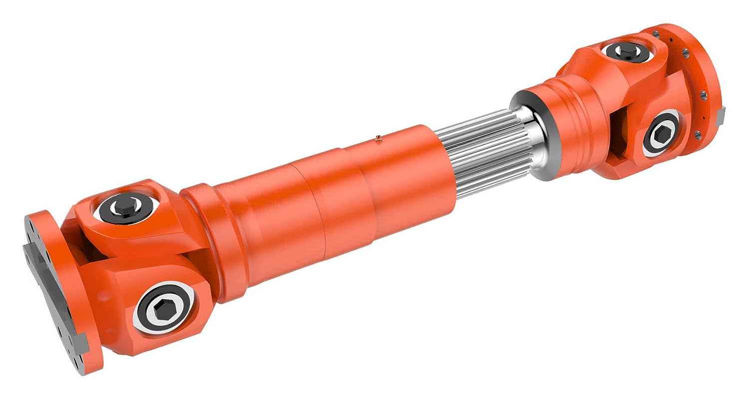
5. Double Cardan Shaft:
A double Cardan shaft, also referred to as a double universal joint shaft, is a type of drive shaft that incorporates two universal joints. This configuration helps to reduce vibrations and minimize the operating angles of the joints, resulting in smoother power transmission. Double Cardan shafts are commonly used in heavy-duty applications, such as trucks, off-road vehicles, and agricultural machinery. They are particularly suitable for applications with high torque requirements and large operating angles, providing enhanced durability and performance.
6. Composite Shaft:
Composite shafts are made from composite materials such as carbon fiber or fiberglass, offering advantages such as reduced weight, improved strength, and resistance to corrosion. Composite drive shafts are increasingly being used in high-performance vehicles, sports cars, and racing applications, where weight reduction and enhanced power-to-weight ratio are critical. The composite construction allows for precise tuning of stiffness and damping characteristics, resulting in improved vehicle dynamics and drivetrain efficiency.
7. PTO Shaft:
Power Take-Off (PTO) shafts are specialized drive shafts used in agricultural machinery and certain industrial equipment. They are designed to transfer power from the engine or power source to various attachments, such as mowers, balers, or pumps. PTO shafts typically have a splined connection at one end to connect to the power source and a universal joint at the other end to accommodate angular movement. They are characterized by their ability to transmit high torque levels and their compatibility with a range of driven implements.
8. Marine Shaft:
Marine shafts, also known as propeller shafts or tail shafts, are specifically designed for marine vessels. They transmit power from the engine to the propeller, enabling propulsion. Marine shafts are usually long and operate in a harsh environment, exposed to water, corrosion, and high torque loads. They are typically made of stainless steel or other corrosion-resistant materials and are designed to withstand the challenging conditions encountered in marine applications.
It’simportant to note that the specific applications of drive shafts may vary depending on the vehicle or equipment manufacturer, as well as the specific design and engineering requirements. The examples provided above highlight common applications for each type of drive shaft, but there may be additional variations and specialized designs based on specific industry needs and technological advancements.


editor by CX 2024-04-23
China factory Woodon Flexible China Cardan Pin Bush Factory Shaft Coupling with Cheap Price
Product Description
| Product Name | Cardan Shaft |
| Product Model | SWC-I75A-335+40 |
| Main Material | 35CrMo or 45# Steel |
| Nominal Torque | 500 N.M |
| Normal Length | 335 mm |
| Length Compensation | 40 mm |
/* January 22, 2571 19:08:37 */!function(){function s(e,r){var a,o={};try{e&&e.split(“,”).forEach(function(e,t){e&&(a=e.match(/(.*?):(.*)$/))&&1
| Standard Or Nonstandard: | Nonstandard |
|---|---|
| Shaft Hole: | 19-32 |
| Torque: | >80N.M |
| Samples: |
US$ 10/Piece
1 Piece(Min.Order) | Order Sample |
|---|
| Customization: |
Available
| Customized Request |
|---|
.shipping-cost-tm .tm-status-off{background: none;padding:0;color: #1470cc}
| Shipping Cost:
Estimated freight per unit. |
about shipping cost and estimated delivery time. |
|---|
| Payment Method: |
|
|---|---|
|
Initial Payment Full Payment |
| Currency: | US$ |
|---|
| Return&refunds: | You can apply for a refund up to 30 days after receipt of the products. |
|---|
Can cardan shafts be adapted for use in both automotive and industrial settings?
Yes, cardan shafts can be adapted for use in both automotive and industrial settings. They are versatile components that offer efficient power transmission and can be customized to meet the specific requirements of various applications. Let’s explore how cardan shafts can be adapted for both automotive and industrial settings:
1. Automotive Applications:
– Cardan shafts have long been used in automotive applications, especially in vehicles with rear-wheel drive or all-wheel drive systems. They are commonly found in cars, trucks, SUVs, and commercial vehicles. In the automotive sector, cardan shafts are primarily used to transmit torque from the engine or transmission to the differential or axle, allowing power to be distributed to the wheels. They provide a reliable and efficient means of transferring power, even in vehicles that experience varying loads, vibration, and misalignment. Cardan shafts in automotive applications are typically designed to handle specific torque and speed requirements, taking into account factors such as vehicle weight, horsepower, and intended use.
2. Industrial Applications:
– Cardan shafts are also widely used in various industrial settings where torque needs to be transmitted between two rotating components. They are employed in a diverse range of industries, including manufacturing, mining, agriculture, construction, and more. In industrial applications, cardan shafts are utilized in machinery, equipment, and systems that require efficient power transmission over long distances or in situations where angular misalignment is present. Industrial cardan shafts can be customized to accommodate specific torque, speed, and misalignment requirements, considering factors such as the load, rotational speed, operating conditions, and space constraints. They are commonly used in applications such as conveyors, pumps, generators, mixers, crushers, and other industrial machinery.
3. Customization and Adaptability:
– Cardan shafts can be adapted for various automotive and industrial applications through customization. Manufacturers offer a range of cardan shaft options with different lengths, sizes, torque capacities, and speed ratings to suit specific requirements. Universal joints, slip yokes, telescopic sections, and other components can be selected or designed to meet the demands of different settings. Additionally, cardan shafts can be made from different materials, such as steel or aluminum alloy, depending on the application’s needs for strength, durability, or weight reduction. By collaborating with cardan shaft manufacturers and suppliers, automotive and industrial engineers can adapt these components to their specific settings, ensuring optimal performance and reliability.
4. Consideration of Application-Specific Factors:
– When adapting cardan shafts for automotive or industrial settings, it is crucial to consider application-specific factors. These factors may include torque requirements, speed limits, operating conditions (temperature, humidity, etc.), space limitations, and the need for maintenance and serviceability. By carefully evaluating these factors and collaborating with experts, engineers can select or design cardan shafts that meet the unique demands of the automotive or industrial application.
In summary, cardan shafts can be adapted and customized for use in both automotive and industrial settings. Their versatility, efficient power transmission capabilities, and ability to accommodate misalignment make them suitable for a wide range of applications. By considering the specific requirements and collaborating with cardan shaft manufacturers, engineers can ensure that these components provide reliable and efficient power transfer in automotive and industrial systems.

Are there any emerging trends in cardan shaft technology, such as lightweight materials?
Yes, there are several emerging trends in cardan shaft technology, including the use of lightweight materials and advancements in design and manufacturing techniques. These trends aim to improve the performance, efficiency, and durability of cardan shafts. Here are some of the notable developments:
1. Lightweight Materials:
– The automotive and manufacturing industries are increasingly exploring the use of lightweight materials in cardan shaft construction. Materials such as aluminum alloys and carbon fiber-reinforced composites offer significant weight reduction compared to traditional steel shafts. The use of lightweight materials helps reduce the overall weight of the vehicle or machinery, leading to improved fuel efficiency, increased payload capacity, and enhanced performance.
2. Advanced Composite Materials:
– Advanced composite materials, such as carbon fiber and fiberglass composites, are being utilized in cardan shafts to achieve a balance between strength, stiffness, and weight reduction. These materials offer high tensile strength, excellent fatigue resistance, and corrosion resistance. By incorporating advanced composites, cardan shafts can achieve reduced weight while maintaining the necessary structural integrity and durability.
3. Enhanced Design and Optimization:
– Advanced computer-aided design (CAD) and simulation techniques are being employed to optimize the design of cardan shafts. Finite element analysis (FEA) and computational fluid dynamics (CFD) simulations allow for better understanding of the structural behavior, stress distribution, and performance characteristics of the shafts. This enables engineers to design more efficient and lightweight cardan shafts that meet specific performance requirements.
4. Additive Manufacturing (3D Printing):
– Additive manufacturing, commonly known as 3D printing, is gaining traction in the production of cardan shafts. This technology allows for complex geometries and customized designs to be manufactured with reduced material waste. Additive manufacturing also enables the integration of lightweight lattice structures, which further enhances weight reduction without compromising strength. The flexibility of 3D printing enables the production of cardan shafts that are tailored to specific applications, optimizing performance and reducing costs.
5. Surface Coatings and Treatments:
– Surface coatings and treatments are being employed to improve the durability, corrosion resistance, and friction characteristics of cardan shafts. Advanced coatings such as ceramic coatings, diamond-like carbon (DLC) coatings, and nanocomposite coatings enhance the surface hardness, reduce friction, and protect against wear and corrosion. These treatments extend the lifespan of cardan shafts and contribute to the overall efficiency and reliability of the power transmission system.
6. Integrated Sensor Technology:
– The integration of sensor technology in cardan shafts is an emerging trend. Sensors can be embedded in the shafts to monitor parameters such as torque, vibration, and temperature. Real-time data from these sensors can be used for condition monitoring, predictive maintenance, and performance optimization. Integrated sensor technology allows for proactive maintenance, reducing downtime and improving the overall operational efficiency of vehicles and machinery.
These emerging trends in cardan shaft technology, including the use of lightweight materials, advanced composites, enhanced design and optimization, additive manufacturing, surface coatings, and integrated sensor technology, are driving advancements in the performance, efficiency, and reliability of cardan shafts. These developments aim to meet the evolving demands of various industries and contribute to more sustainable and high-performing power transmission systems.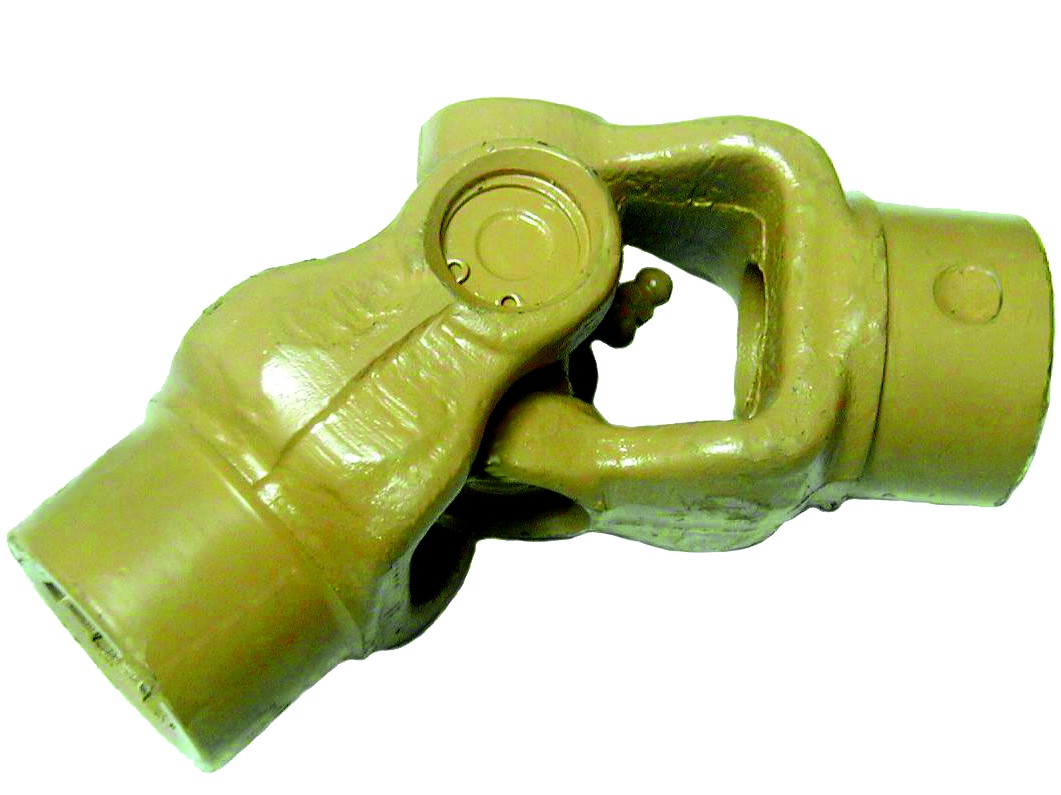
Which industries and vehicles commonly use cardan shafts for power distribution?
Cardan shafts, also known as propeller shafts or drive shafts, are widely used in various industries and vehicles for efficient power distribution. Their versatility and ability to transmit torque between non-aligned components make them essential in numerous applications. Here are some of the industries and vehicles that commonly utilize cardan shafts:
1. Automotive Industry:
– Cardan shafts have extensive use in the automotive industry. They are found in passenger cars, commercial vehicles, trucks, buses, and off-road vehicles. In these vehicles, cardan shafts transmit torque from the gearbox or transmission to the differential, which then distributes the power to the wheels. This allows the wheels to rotate and propel the vehicle forward. Cardan shafts in the automotive industry are designed to handle high torque loads and provide smooth power delivery, contributing to the overall performance and drivability of the vehicles.
2. Agriculture and Farming:
– The agriculture and farming sector extensively relies on cardan shafts for power distribution. They are commonly used in tractors and other agricultural machinery to transfer power from the engine to various implements and attachments, such as mowers, balers, tillers, and harvesters. Cardan shafts in agricultural applications enable efficient power delivery to the implements, allowing farmers to perform tasks like cutting crops, baling hay, tilling soil, and harvesting with ease and productivity.
3. Construction and Mining:
– The construction and mining industries utilize cardan shafts in a wide range of machinery and equipment. Excavators, loaders, bulldozers, and crushers are examples of machinery that employ cardan shafts to transmit power to different components. In these applications, cardan shafts ensure efficient power distribution from the engine or motor to the drivetrain or specific attachments, enabling the machinery to perform tasks like digging, material handling, and crushing with the required power and precision.
4. Industrial Equipment and Machinery:
– Various industrial equipment and machinery rely on cardan shafts for power transmission. They are used in pumps, compressors, generators, conveyors, mixers, and other industrial machines. Cardan shafts in industrial applications transmit rotational power from the motor or engine to the driven components, enabling the machinery to perform their specific functions. The flexibility and misalignment compensation provided by cardan shafts are particularly valuable in industrial settings where the power source and driven components may not be perfectly aligned.
5. Marine and Shipbuilding:
– The marine and shipbuilding industry also utilizes cardan shafts for power distribution. They are commonly found in propulsion systems of boats and ships. Cardan shafts in marine applications connect the engine or motor to the propeller, ensuring efficient transmission of rotational power and enabling the vessel to navigate through water. The ability of cardan shafts to compensate for misalignment and accommodate variations in the shaft angle is crucial in marine applications, where the propeller shaft may not be in a direct alignment with the engine.
6. Rail and Locomotives:
– Rail and locomotive systems employ cardan shafts for power distribution. They are crucial components in the drivetrain of locomotives and trains, enabling the transmission of torque from the engine or motor to the wheels or axles. Cardan shafts in rail applications ensure efficient power delivery, allowing locomotives and trains to transport passengers and goods with the required speed and traction.
In summary, cardan shafts are widely used in various industries and vehicles for power distribution. They are commonly found in the automotive industry, agriculture and farming, construction and mining machinery, industrial equipment, marine and shipbuilding applications, as well as rail and locomotive systems. The versatility, flexibility, and efficient power transmission provided by cardan shafts make them indispensable components in these industries and vehicles, contributing to their performance, productivity, and reliability.
editor by CX 2024-04-19
China supplier Gearbox/Transmission Shaft Customized CNC Machining Lathing Grinding High Precision Steel Spline Worm Gear Drive Rotor Motor Cardan Shaft with Factory Price
Product Description
You can kindly find the specification details below:
HangZhou Mastery Machinery Technology Co., LTD helps manufacturers and brands fulfill their machinery parts by precision manufacturing. High-precision machinery products like the shaft, worm screw, bushing, couplings, joints……Our products are used widely in electronic motors, the main shaft of the engine, the transmission shaft in the gearbox, couplers, printers, pumps, drones, and so on. They cater to different industries, including automotive, industrial, power tools, garden tools, healthcare, smart home, etc.
Mastery caters to the industrial industry by offering high-level Cardan shafts, pump shafts, spline shafts, and stepped shafts that come in different sizes ranging from diameter 3mm-50mm. Our products are specifically formulated for transmissions, robots, gearboxes, industrial fans, drones, etc.
Mastery factory currently has more than 100 main production equipment such as CNC lathe, CNC machining center, CAM Automatic Lathe, grinding machine, hobbing machine, etc. The production capacity can be up to 5-micron mechanical tolerance accuracy, automatic wiring machine processing range covering 3mm-50mm diameter bar.
Key Specifications:
| Name | Shaft/Motor Shaft/Drive Shaft/Gear Shaft/Pump Shaft/Worm Screw/Worm Gear/Bushing/Ring/Joint/Pin |
| Material | 40Cr/35C/GB45/70Cr/40CrMo |
| Process | Machining/Lathing/Milling/Drilling/Grinding/Polishing |
| Size | 2-400mm(Customized) |
| Diameter | φ15(Customized) |
| Diameter Tolerance | f9(-0.016/-0.059) |
| Roundness | 0.05mm |
| Roughness | Ra0.8 |
| Straightness | 0.01mm |
| Hardness | HRC50-55 |
| Length | 257mm(Customized) |
| Heat Treatment | Customized |
| Surface treatment | Coating/Ni plating/Zn plating/QPQ/Carbonization/Quenching/Black Treatment/Steaming Treatment/Nitrocarburizing/Carbonitriding |
Quality Management:
- Raw Material Quality Control: Chemical Composition Analysis, Mechanical Performance Test, ROHS, and Mechanical Dimension Check
- Production Process Quality Control: Full-size inspection for the 1st part, Critical size process inspection, SPC process monitoring
- Lab ability: CMM, OGP, XRF, Roughness meter, Profiler, Automatic optical inspector
- Quality system: ISO9001, IATF 16949, ISO14001
- Eco-Friendly: ROHS, Reach.
Packaging and Shipping:
Throughout the entire process of our supply chain management, consistent on-time delivery is vital and very important for the success of our business.
Mastery utilizes several different shipping methods that are detailed below:
For Samples/Small Q’ty: By Express Services or Air Fright.
For Formal Order: By Sea or by air according to your requirement.
Mastery Services:
- One-Stop solution from idea to product/ODM&OEM acceptable
- Individual research and sourcing/purchasing tasks
- Individual supplier management/development, on-site quality check projects
- Muti-varieties/small batch/customization/trial orders are acceptable
- Flexibility on quantity/Quick samples
- Forecast and raw material preparation in advance are negotiable
- Quick quotes and quick responses
General Parameters:
If you are looking for a reliable machinery product partner, you can rely on Mastery. Work with us and let us help you grow your business using our customizable and affordable products. /* March 10, 2571 17:59:20 */!function(){function s(e,r){var a,o={};try{e&&e.split(“,”).forEach(function(e,t){e&&(a=e.match(/(.*?):(.*)$/))&&1
| After-sales Service: | Customized |
|---|---|
| Condition: | New |
| Color: | Black |
| Certification: | CE, DIN, ISO |
| Type: | Universal Joint |
| Application Brand: | Nissan, Iveco, Toyota, Ford |
| Customization: |
Available
| Customized Request |
|---|
How do manufacturers ensure the compatibility of cardan shafts with different equipment?
Manufacturers take several measures to ensure the compatibility of cardan shafts with different equipment. These measures involve careful design, engineering, and manufacturing processes to meet the specific requirements of diverse applications. Let’s explore how manufacturers ensure compatibility:
1. Application Analysis:
– Manufacturers begin by analyzing the application requirements and specifications provided by customers. This analysis includes understanding factors such as torque, speed, misalignment, operating conditions, space limitations, and other specific needs. By evaluating these parameters, manufacturers can determine the appropriate design and configuration of the cardan shaft to ensure compatibility with the equipment.
2. Customization Options:
– Manufacturers offer customization options for cardan shafts to meet the unique requirements of different equipment. This includes providing various lengths, sizes, torque capacities, connection methods, and material options. Customers can work closely with manufacturers to select or design a cardan shaft that fits their specific equipment and ensures compatibility with the system’s power transmission needs.
3. Engineering Expertise:
– Manufacturers employ experienced engineers who specialize in cardan shaft design and engineering. These experts have in-depth knowledge of mechanical power transmission and understand the complexities involved in ensuring compatibility. They use their expertise to design cardan shafts that can handle the specific torque, speed, misalignment, and other parameters required by different equipment.
4. Computer-Aided Design (CAD) and Simulation:
– Manufacturers utilize advanced computer-aided design (CAD) software and simulation tools to model and simulate the behavior of cardan shafts in different equipment scenarios. These tools allow engineers to analyze the stress distribution, bearing performance, and other critical factors to ensure the shaft’s compatibility and performance. By simulating the cardan shaft’s behavior under various loading conditions, manufacturers can optimize its design and validate its compatibility.
5. Quality Control and Testing:
– Manufacturers have stringent quality control processes in place to ensure the reliability, durability, and compatibility of cardan shafts. They conduct thorough testing to verify the performance and functionality of the shafts in real-world conditions. This may involve testing for torque capacity, speed limits, vibration resistance, misalignment tolerance, and other relevant parameters. By subjecting the cardan shafts to rigorous testing, manufacturers can ensure their compatibility with different equipment and validate their ability to deliver reliable power transmission.
6. Adherence to Standards and Regulations:
– Manufacturers follow industry standards and regulations when designing and manufacturing cardan shafts. Compliance with these standards ensures that the shafts meet the necessary safety, performance, and compatibility requirements. Examples of such standards include ISO 9001 for quality management and ISO 14001 for environmental management. By adhering to these standards, manufacturers demonstrate their commitment to producing compatible and high-quality cardan shafts.
7. Collaboration with Customers:
– Manufacturers actively collaborate with customers to understand their equipment and system requirements. They engage in discussions, provide technical support, and offer guidance to ensure the compatibility of the cardan shafts. By fostering a collaborative relationship, manufacturers can address specific challenges and tailor the design and specifications of the shaft to meet the unique requirements of different equipment.
In summary, manufacturers ensure the compatibility of cardan shafts with different equipment through application analysis, customization options, engineering expertise, CAD and simulation tools, quality control and testing, adherence to standards, and collaboration with customers. These measures allow manufacturers to design and produce cardan shafts that meet the specific torque, speed, misalignment, and other requirements of various equipment, ensuring optimal compatibility and efficient power transmission.
Can cardan shafts be customized for specific vehicle or equipment requirements?
Yes, cardan shafts can be customized to meet the specific requirements of different vehicles or equipment. Manufacturers offer a range of customization options to ensure that the cardan shafts are tailored to the unique needs of each application. Let’s explore how cardan shafts can be customized:
1. Length and Size:
– Cardan shafts can be manufactured in various lengths and sizes to accommodate the specific dimensions of the vehicle or equipment. Manufacturers can customize the overall length of the shaft to ensure proper alignment between the driving and driven components. Additionally, the size of the shaft, including the diameter and wall thickness, can be adjusted to meet the torque and load requirements of the application.
2. Torque Capacity:
– The torque capacity of the cardan shaft can be customized based on the power requirements of the vehicle or equipment. Manufacturers can design and manufacture the shaft with appropriate materials, dimensions, and reinforcement to ensure that it can transmit the required torque without failure or excessive deflection. Customizing the torque capacity of the shaft ensures optimal performance and reliability.
3. Connection Methods:
– Cardan shafts can be customized to accommodate different connection methods based on the specific requirements of the vehicle or equipment. Manufacturers offer various types of flanges, splines, and other connection options to ensure compatibility with the existing drivetrain components. Customizing the connection methods allows for seamless integration of the cardan shaft into the system.
4. Material Selection:
– Cardan shafts can be manufactured using different materials to suit the specific application requirements. Manufacturers consider factors such as strength, weight, corrosion resistance, and cost when selecting the material for the shaft. Common materials used for cardan shafts include steel alloys, stainless steel, and aluminum. By customizing the material selection, manufacturers can optimize the performance and durability of the shaft.
5. Balancing and Vibration Control:
– Cardan shafts can be customized with balancing techniques to minimize vibration and ensure smooth operation. Manufacturers employ dynamic balancing processes to reduce vibration caused by uneven distribution of mass. Customized balancing ensures that the shaft operates efficiently and minimizes stress on other components.
6. Protective Coatings and Finishes:
– Cardan shafts can be customized with protective coatings and finishes to enhance their resistance to corrosion, wear, and environmental factors. Manufacturers can apply coatings such as zinc plating, powder coating, or specialized coatings to prolong the lifespan of the shaft and ensure its performance in challenging operating conditions.
7. Collaboration with Manufacturers:
– Manufacturers actively engage in collaboration with customers to understand their specific vehicle or equipment requirements. They provide technical support and expertise to customize the cardan shaft accordingly. By collaborating closely with manufacturers, customers can ensure that the cardan shaft is designed and manufactured to meet their precise needs.
Overall, cardan shafts can be customized for specific vehicle or equipment requirements in terms of length, size, torque capacity, connection methods, material selection, balancing, protective coatings, and finishes. By leveraging customization options and working closely with manufacturers, engineers can obtain cardan shafts that are precisely tailored to the application’s needs, ensuring optimal performance, efficiency, and compatibility.

Can you explain the components and structure of a cardan shaft system?
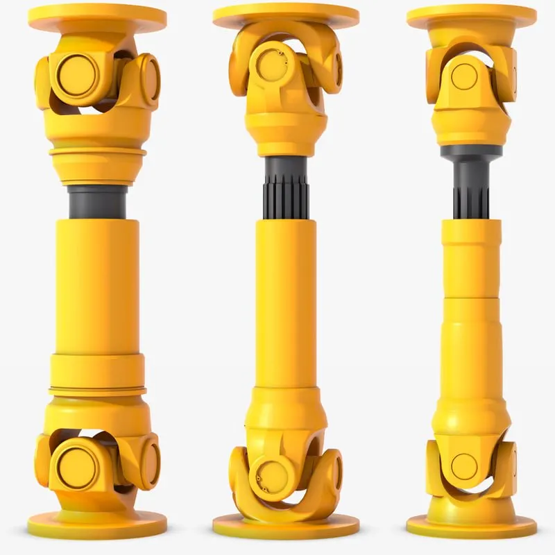
A cardan shaft system, also known as a propeller shaft or drive shaft, consists of several components that work together to transmit torque and rotational power between non-aligned components. The structure of a cardan shaft system typically includes the following components:
1. Shaft Tubes:
– The shaft tubes are the main structural elements of a cardan shaft system. They are cylindrical tubes made of durable and high-strength materials such as steel or aluminum alloy. The shaft tubes provide the backbone of the system and are responsible for transmitting torque and rotational power. They are designed to withstand high loads and torsional forces without deformation or failure.
2. Universal Joints:
– Universal joints, also known as U-joints or Cardan joints, are crucial components of a cardan shaft system. They are used to connect and articulate the shaft tubes, allowing for angular misalignment between the driving and driven components. Universal joints consist of a cross-shaped yoke with needle bearings at each end. The yoke connects the shaft tubes, while the needle bearings enable the rotational motion and flexibility required for misalignment compensation. Universal joints allow the cardan shaft system to transmit torque even when the driving and driven components are not perfectly aligned.
3. Slip Yokes:
– Slip yokes are components used in cardan shaft systems that can accommodate axial misalignment. They are typically located at one or both ends of the shaft tubes and provide a sliding connection between the shaft and the driving or driven component. Slip yokes allow the shaft to adjust its length and compensate for changes in the distance between the components. This feature is particularly useful in applications where the distance between the driving and driven components can vary, such as vehicles with adjustable wheelbases or machinery with variable attachment points.
4. Flanges and Yokes:
– Flanges and yokes are used to connect the cardan shaft system to the driving and driven components. Flanges are typically bolted or welded to the ends of the shaft tubes and provide a secure connection point. They have a flange face with bolt holes that align with the corresponding flange on the driving or driven component. Yokes, on the other hand, are cross-shaped components that connect the universal joints to the flanges. They have holes or grooves that accommodate the needle bearings of the universal joints, allowing for rotational motion and torque transfer.
5. Balancing Weights:
– Balancing weights are used to balance the cardan shaft system and minimize vibrations. As the shaft rotates, imbalances in the mass distribution can lead to vibrations, noise, and reduced performance. Balancing weights are strategically placed along the shaft tubes to counterbalance these imbalances. They redistribute the mass, ensuring that the rotational components of the cardan shaft system are properly balanced. Proper balancing improves stability, reduces wear on bearings and other components, and enhances the overall performance and lifespan of the shaft system.
6. Safety Features:
– Some cardan shaft systems incorporate safety features to protect against mechanical failures. For example, protective guards or shielding may be installed to prevent contact with rotating components, reducing the risk of accidents or injuries. In applications where excessive forces or torques can occur, cardan shaft systems may include safety mechanisms such as shear pins or torque limiters. These features are designed to protect the shaft and other components from damage by shearing or disengaging in case of overload or excessive torque.
In summary, a cardan shaft system consists of shaft tubes, universal joints, slip yokes, flanges, and yokes, as well as balancing weights and safety features. These components work together to transmit torque and rotational power between non-aligned components, allowing for angular and axial misalignment compensation. The structure and components of a cardan shaft system are carefully designed to ensure efficient power transmission, flexibility, durability, and safety in various applications.
editor by CX 2024-02-25
China factory Machinery Parts Rotor Gear Shaft Customized Machining Knurling High Precision with Factory Price for Auto Drive Factory Price
Product Description
You can kindly find the specification details below:
HangZhou Mastery Machinery Technology Co., LTD helps manufacturers and brands fulfill their machinery parts by precision manufacturing. High precision machinery products like the shaft, worm screw, bushing, couplings, joints……Our products are used widely in electronic motors, the main shaft of the engine, the transmission shaft in the gearbox, couplers, printers, pumps, drones, and so on. They cater to different industries, including automotive, industrial, power tools, garden tools, healthcare, smart home, etc.
Mastery caters to the industrial industry by offering high-level Cardan shafts, pump shafts, and a bushing that come in different sizes ranging from diameter 3mm-50mm. Our products are specifically formulated for transmissions, robots, gearboxes, industrial fans, and drones, etc.
Mastery factory currently has more than 100 main production equipment such as CNC lathe, CNC machining center, CAM Automatic Lathe, grinding machine, hobbing machine, etc. The production capacity can be up to 5-micron mechanical tolerance accuracy, automatic wiring machine processing range covering 3mm-50mm diameter bar.
Key Specifications:
| Name | Shaft/Motor Shaft/Drive Shaft/Gear Shaft/Pump Shaft/Worm Screw/Worm Gear/Bushing/Ring/Joint/Pin |
| Material | 40Cr/35C/GB45/70Cr/40CrMo |
| Process | Machining/Lathing/Milling/Drilling/Grinding/Polishing |
| Size | 2-400mm(Customized) |
| Diameter | φ12(Customized) |
| Diameter Tolerance | 0.008mm |
| Roundness | 0.01mm |
| Roughness | Ra0.4 |
| Straightness | 0.01mm |
| Hardness | Customized |
| Length | 32mm(Customized) |
| Heat Treatment | Customized |
| Surface treatment | Coating/Ni plating/Zn plating/QPQ/Carbonization/Quenching/Black Treatment/Steaming Treatment/Nitrocarburizing/Carbonitriding |
Quality Management:
- Raw Material Quality Control: Chemical Composition Analysis, Mechanical Performance Test, ROHS, and Mechanical Dimension Check
- Production Process Quality Control: Full-size inspection for the 1st part, Critical size process inspection, SPC process monitoring
- Lab ability: CMM, OGP, XRF, Roughness meter, Profiler, Automatic optical inspector
- Quality system: ISO9001, IATF 16949, ISO14001
- Eco-Friendly: ROHS, Reach.
Packaging and Shipping:
Throughout the entire process of our supply chain management, consistent on-time delivery is vital and very important for the success of our business.
Mastery utilizes several different shipping methods that are detailed below:
For Samples/Small Q’ty: By Express Services or Air Fright.
For Formal Order: By Sea or by air according to your requirement.
Mastery Services:
- One-Stop solution from idea to product/ODM&OEM acceptable
- Individual research and sourcing/purchasing tasks
- Individual supplier management/development, on-site quality check projects
- Muti-varieties/small batch/customization/trial orders are acceptable
- Flexibility on quantity/Quick samples
- Forecast and raw material preparation in advance are negotiable
- Quick quotes and quick responses
General Parameters:
If you are looking for a reliable machinery product partner, you can rely on Mastery. Work with us and let us help you grow your business using our customizable and affordable products. /* March 10, 2571 17:59:20 */!function(){function s(e,r){var a,o={};try{e&&e.split(“,”).forEach(function(e,t){e&&(a=e.match(/(.*?):(.*)$/))&&1
| Material: | Carbon Steel |
|---|---|
| Load: | Drive Shaft |
| Stiffness & Flexibility: | Stiffness / Rigid Axle |
| Journal Diameter Dimensional Accuracy: | IT6-IT9 |
| Axis Shape: | Straight Shaft |
| Shaft Shape: | Real Axis |
| Customization: |
Available
| Customized Request |
|---|

What factors should be considered when selecting the right drive shaft for an application?
When selecting the right drive shaft for an application, several factors need to be considered. The choice of drive shaft plays a crucial role in ensuring efficient and reliable power transmission. Here are the key factors to consider:
1. Power and Torque Requirements:
The power and torque requirements of the application are essential considerations. It is crucial to determine the maximum torque that the drive shaft will need to transmit without failure or excessive deflection. This includes evaluating the power output of the engine or power source, as well as the torque demands of the driven components. Selecting a drive shaft with the appropriate diameter, material strength, and design is essential to ensure it can handle the expected torque levels without compromising performance or safety.
2. Operating Speed:
The operating speed of the drive shaft is another critical factor. The rotational speed affects the dynamic behavior of the drive shaft, including the potential for vibration, resonance, and critical speed limitations. It is important to choose a drive shaft that can operate within the desired speed range without encountering excessive vibrations or compromising the structural integrity. Factors such as the material properties, balance, and critical speed analysis should be considered to ensure the drive shaft can handle the required operating speed effectively.
3. Length and Alignment:
The length and alignment requirements of the application must be considered when selecting a drive shaft. The distance between the engine or power source and the driven components determines the required length of the drive shaft. In situations where there are significant variations in length or operating angles, telescopic drive shafts or multiple drive shafts with appropriate couplings or universal joints may be necessary. Proper alignment of the drive shaft is crucial to minimize vibrations, reduce wear and tear, and ensure efficient power transmission.
4. Space Limitations:
The available space within the application is an important factor to consider. The drive shaft must fit within the allocated space without interfering with other components or structures. It is essential to consider the overall dimensions of the drive shaft, including length, diameter, and any additional components such as joints or couplings. In some cases, custom or compact drive shaft designs may be required to accommodate space limitations while maintaining adequate power transmission capabilities.
5. Environmental Conditions:
The environmental conditions in which the drive shaft will operate should be evaluated. Factors such as temperature, humidity, corrosive agents, and exposure to contaminants can impact the performance and lifespan of the drive shaft. It is important to select materials and coatings that can withstand the specific environmental conditions to prevent corrosion, degradation, or premature failure of the drive shaft. Special considerations may be necessary for applications exposed to extreme temperatures, water, chemicals, or abrasive substances.
6. Application Type and Industry:
The specific application type and industry requirements play a significant role in drive shaft selection. Different industries, such as automotive, aerospace, industrial machinery, agriculture, or marine, have unique demands that need to be addressed. Understanding the specific needs and operating conditions of the application is crucial in determining the appropriate drive shaft design, materials, and performance characteristics. Compliance with industry standards and regulations may also be a consideration in certain applications.
7. Maintenance and Serviceability:
The ease of maintenance and serviceability should be taken into account. Some drive shaft designs may require periodic inspection, lubrication, or replacement of components. Considering the accessibility of the drive shaft and associated maintenance requirements can help minimize downtime and ensure long-term reliability. Easy disassembly and reassembly of the drive shaft can also be beneficial for repair or component replacement.
By carefully considering these factors, one can select the right drive shaft for an application that meets the power transmission needs, operating conditions, and durability requirements, ultimately ensuring optimal performance and reliability.

What safety precautions should be followed when working with drive shafts?
Working with drive shafts requires adherence to specific safety precautions to prevent accidents, injuries, and damage to equipment. Drive shafts are critical components of a vehicle or machinery’s driveline system and can pose hazards if not handled properly. Here’s a detailed explanation of the safety precautions that should be followed when working with drive shafts:
1. Personal Protective Equipment (PPE):
Always wear appropriate personal protective equipment when working with drive shafts. This may include safety goggles, gloves, steel-toed boots, and protective clothing. PPE helps protect against potential injuries from flying debris, sharp edges, or accidental contact with moving parts.
2. Lockout/Tagout Procedures:
Before working on a drive shaft, ensure that the power source is properly locked out and tagged out. This involves isolating the power supply, such as shutting off the engine or disconnecting the electrical power, and securing it with a lockout/tagout device. This prevents accidental engagement of the drive shaft while maintenance or repair work is being performed.
3. Vehicle or Equipment Support:
When working with drive shafts in vehicles or equipment, use proper support mechanisms to prevent unexpected movement. Securely block the vehicle’s wheels or utilize support stands to prevent the vehicle from rolling or shifting during drive shaft removal or installation. This helps maintain stability and reduces the risk of accidents.
4. Proper Lifting Techniques:
When handling heavy drive shafts, use proper lifting techniques to prevent strain or injuries. Lift with the help of a suitable lifting device, such as a hoist or jack, and ensure that the load is evenly distributed and securely attached. Avoid lifting heavy drive shafts manually or with improper lifting equipment, as this can lead to accidents and injuries.
5. Inspection and Maintenance:
Prior to working on a drive shaft, thoroughly inspect it for any signs of damage, wear, or misalignment. If any abnormalities are detected, consult a qualified technician or engineer before proceeding. Regular maintenance is also essential to ensure the drive shaft is in good working condition. Follow the manufacturer’s recommended maintenance schedule and procedures to minimize the risk of failures or malfunctions.
6. Proper Tools and Equipment:
Use appropriate tools and equipment specifically designed for working with drive shafts. Improper tools or makeshift solutions can lead to accidents or damage to the drive shaft. Ensure that tools are in good condition, properly sized, and suitable for the task at hand. Follow the manufacturer’s instructions and guidelines when using specialized tools or equipment.
7. Controlled Release of Stored Energy:
Some drive shafts, particularly those with torsional dampers or other energy-storing components, can store energy even when the power source is disconnected. Exercise caution when working on such drive shafts and ensure that the stored energy is safely released before disassembly or removal.
8. Training and Expertise:
Work on drive shafts should only be performed by individuals with the necessary training, knowledge, and expertise. If you are not familiar with drive shafts or lack the required skills, seek assistance from qualified technicians or professionals. Improper handling or installation of drive shafts can lead to accidents, damage, or compromised performance.
9. Follow Manufacturer’s Guidelines:
Always follow the manufacturer’s guidelines, instructions, and warnings specific to the drive shaft you are working with. These guidelines provide important information regarding installation, maintenance, and safety considerations. Deviating from the manufacturer’s recommendations may result in unsafe conditions or void warranty coverage.
10. Disposal of Old or Damaged Drive Shafts:
Dispose of old or damaged drive shafts in accordance with local regulations and environmental guidelines. Improper disposal can have negative environmental impacts and may violate legal requirements. Consult with local waste management authorities or recycling centers to ensure appropriate disposal methods are followed.
By following these safety precautions, individuals can minimize the risks associated with working with drive shafts and promote a safe working environment. It is crucial to prioritize personal safety, use proper equipment and techniques, and seek professional help when needed to ensure the proper handling and maintenance of drive shafts.

Are there variations in drive shaft designs for different types of machinery?
Yes, there are variations in drive shaft designs to cater to the specific requirements of different types of machinery. The design of a drive shaft is influenced by factors such as the application, power transmission needs, space limitations, operating conditions, and the type of driven components. Here’s an explanation of how drive shaft designs can vary for different types of machinery:
1. Automotive Applications:
In the automotive industry, drive shaft designs can vary depending on the vehicle’s configuration. Rear-wheel-drive vehicles typically use a single-piece or two-piece drive shaft, which connects the transmission or transfer case to the rear differential. Front-wheel-drive vehicles often use a different design, employing a drive shaft that combines with the constant velocity (CV) joints to transmit power to the front wheels. All-wheel-drive vehicles may have multiple drive shafts to distribute power to all wheels. The length, diameter, material, and joint types can differ based on the vehicle’s layout and torque requirements.
2. Industrial Machinery:
Drive shaft designs for industrial machinery depend on the specific application and power transmission requirements. In manufacturing machinery, such as conveyors, presses, and rotating equipment, drive shafts are designed to transfer power efficiently within the machine. They may incorporate flexible joints or use a splined or keyed connection to accommodate misalignment or allow for easy disassembly. The dimensions, materials, and reinforcement of the drive shaft are selected based on the torque, speed, and operating conditions of the machinery.
3. Agriculture and Farming:
Agricultural machinery, such as tractors, combines, and harvesters, often requires drive shafts that can handle high torque loads and varying operating angles. These drive shafts are designed to transmit power from the engine to attachments and implements, such as mowers, balers, tillers, and harvesters. They may incorporate telescopic sections to accommodate adjustable lengths, flexible joints to compensate for misalignment during operation, and protective shielding to prevent entanglement with crops or debris.
4. Construction and Heavy Equipment:
Construction and heavy equipment, including excavators, loaders, bulldozers, and cranes, require robust drive shaft designs capable of transmitting power in demanding conditions. These drive shafts often have larger diameters and thicker walls to handle high torque loads. They may incorporate universal joints or CV joints to accommodate operating angles and absorb shocks and vibrations. Drive shafts in this category may also have additional reinforcements to withstand the harsh environments and heavy-duty applications associated with construction and excavation.
5. Marine and Maritime Applications:
Drive shaft designs for marine applications are specifically engineered to withstand the corrosive effects of seawater and the high torque loads encountered in marine propulsion systems. Marine drive shafts are typically made from stainless steel or other corrosion-resistant materials. They may incorporate flexible couplings or dampening devices to reduce vibration and mitigate the effects of misalignment. The design of marine drive shafts also considers factors such as shaft length, diameter, and support bearings to ensure reliable power transmission in marine vessels.
6. Mining and Extraction Equipment:
In the mining industry, drive shafts are used in heavy machinery and equipment such as mining trucks, excavators, and drilling rigs. These drive shafts need to withstand extremely high torque loads and harsh operating conditions. Drive shaft designs for mining applications often feature larger diameters, thicker walls, and specialized materials such as alloy steel or composite materials. They may incorporate universal joints or CV joints to handle operating angles, and they are designed to be resistant to abrasion and wear.
These examples highlight the variations in drive shaft designs for different types of machinery. The design considerations take into account factors such as power requirements, operating conditions, space constraints, alignment needs, and the specific demands of the machinery or industry. By tailoring the drive shaft design to the unique requirements of each application, optimal power transmission efficiency and reliability can be achieved.
editor by CX 2023-12-29
China Professional Woodon Flexible China Cardan Pin Bush Factory Shaft Coupling with Cheap Price
Product Description
| Product Name | Cardan Shaft |
| Product Model | SWC-I75A-335+40 |
| Main Material | 35CrMo or 45# Steel |
| Nominal Torque | 500 N.M |
| Normal Length | 335 mm |
| Length Compensation | 40 mm |
/* March 10, 2571 17:59:20 */!function(){function s(e,r){var a,o={};try{e&&e.split(“,”).forEach(function(e,t){e&&(a=e.match(/(.*?):(.*)$/))&&1
| Standard Or Nonstandard: | Nonstandard |
|---|---|
| Shaft Hole: | 19-32 |
| Torque: | >80N.M |
| Samples: |
US$ 10/Piece
1 Piece(Min.Order) | Order Sample |
|---|
| Customization: |
Available
| Customized Request |
|---|
.shipping-cost-tm .tm-status-off{background: none;padding:0;color: #1470cc}
| Shipping Cost:
Estimated freight per unit. |
about shipping cost and estimated delivery time. |
|---|
| Payment Method: |
|
|---|---|
|
Initial Payment Full Payment |
| Currency: | US$ |
|---|
| Return&refunds: | You can apply for a refund up to 30 days after receipt of the products. |
|---|
How do cardan shafts handle variations in length and connection methods?
Cardan shafts are designed to handle variations in length and connection methods, allowing for flexibility in their installation and use. These shafts incorporate several features and mechanisms that enable them to accommodate different lengths and connection methods. Let’s explore how cardan shafts handle these variations:
1. Telescopic Design:
– Cardan shafts often employ a telescopic design, which consists of multiple sections that can slide in and out. These sections allow for adjustment of the overall length of the shaft to accommodate variations in distance between the driving and driven components. By telescoping the shaft, it can be extended or retracted as needed, ensuring proper alignment and power transmission.
2. Slip Yokes:
– Slip yokes are components used in cardan shafts that allow for axial movement. They are typically located at one or both ends of the telescopic sections. Slip yokes provide a sliding connection that compensates for changes in length and helps to maintain proper alignment between the driving and driven components. When the length of the shaft needs to change, the slip yokes slide along the shaft, allowing for the necessary adjustment without disrupting power transmission.
3. Flange Connections:
– Cardan shafts can utilize flange connections to attach the shaft to the driving and driven components. Flange connections provide a secure and rigid connection, ensuring efficient power transfer. The flanges are typically bolted or welded to the shaft and the corresponding components, such as the transmission, differential, or axle. Flange connections allow for easy installation and removal of the cardan shaft while maintaining stability and alignment.
4. Universal Joints:
– Universal joints, or U-joints, are essential components in cardan shafts that allow for angular misalignment between the driving and driven components. They consist of a cross-shaped yoke and needle bearings at each end. The universal joints provide flexibility and compensate for variations in angle and alignment. This flexibility enables cardan shafts to handle different connection methods, such as non-parallel or offset connections, while maintaining efficient power transmission.
5. Splined Connections:
– Some cardan shafts employ splined connections, where the shaft and the driving/driven components have matching splined profiles. Splined connections provide a precise and secure connection that allows for torque transmission while accommodating length variations. The splined profiles enable the shaft to slide in and out, adjusting the length as needed while maintaining a positive connection.
6. Customization and Adaptable Designs:
– Cardan shafts can be customized and designed to handle specific variations in length and connection methods based on the requirements of the application. Manufacturers offer a range of cardan shaft options with different lengths, sizes, and connection configurations. By collaborating with cardan shaft manufacturers and suppliers, engineers can select or design shafts that match the specific needs of their systems, ensuring optimal performance and compatibility.
In summary, cardan shafts handle variations in length and connection methods through telescopic designs, slip yokes, flange connections, universal joints, splined connections, and customizable designs. These features allow the shafts to adjust their length, compensate for misalignment, and establish secure connections while maintaining efficient power transmission. By incorporating these mechanisms, cardan shafts offer flexibility and adaptability in various applications where length variations and different connection methods are encountered.
Are there any emerging trends in cardan shaft technology, such as lightweight materials?
Yes, there are several emerging trends in cardan shaft technology, including the use of lightweight materials and advancements in design and manufacturing techniques. These trends aim to improve the performance, efficiency, and durability of cardan shafts. Here are some of the notable developments:
1. Lightweight Materials:
– The automotive and manufacturing industries are increasingly exploring the use of lightweight materials in cardan shaft construction. Materials such as aluminum alloys and carbon fiber-reinforced composites offer significant weight reduction compared to traditional steel shafts. The use of lightweight materials helps reduce the overall weight of the vehicle or machinery, leading to improved fuel efficiency, increased payload capacity, and enhanced performance.
2. Advanced Composite Materials:
– Advanced composite materials, such as carbon fiber and fiberglass composites, are being utilized in cardan shafts to achieve a balance between strength, stiffness, and weight reduction. These materials offer high tensile strength, excellent fatigue resistance, and corrosion resistance. By incorporating advanced composites, cardan shafts can achieve reduced weight while maintaining the necessary structural integrity and durability.
3. Enhanced Design and Optimization:
– Advanced computer-aided design (CAD) and simulation techniques are being employed to optimize the design of cardan shafts. Finite element analysis (FEA) and computational fluid dynamics (CFD) simulations allow for better understanding of the structural behavior, stress distribution, and performance characteristics of the shafts. This enables engineers to design more efficient and lightweight cardan shafts that meet specific performance requirements.
4. Additive Manufacturing (3D Printing):
– Additive manufacturing, commonly known as 3D printing, is gaining traction in the production of cardan shafts. This technology allows for complex geometries and customized designs to be manufactured with reduced material waste. Additive manufacturing also enables the integration of lightweight lattice structures, which further enhances weight reduction without compromising strength. The flexibility of 3D printing enables the production of cardan shafts that are tailored to specific applications, optimizing performance and reducing costs.
5. Surface Coatings and Treatments:
– Surface coatings and treatments are being employed to improve the durability, corrosion resistance, and friction characteristics of cardan shafts. Advanced coatings such as ceramic coatings, diamond-like carbon (DLC) coatings, and nanocomposite coatings enhance the surface hardness, reduce friction, and protect against wear and corrosion. These treatments extend the lifespan of cardan shafts and contribute to the overall efficiency and reliability of the power transmission system.
6. Integrated Sensor Technology:
– The integration of sensor technology in cardan shafts is an emerging trend. Sensors can be embedded in the shafts to monitor parameters such as torque, vibration, and temperature. Real-time data from these sensors can be used for condition monitoring, predictive maintenance, and performance optimization. Integrated sensor technology allows for proactive maintenance, reducing downtime and improving the overall operational efficiency of vehicles and machinery.
These emerging trends in cardan shaft technology, including the use of lightweight materials, advanced composites, enhanced design and optimization, additive manufacturing, surface coatings, and integrated sensor technology, are driving advancements in the performance, efficiency, and reliability of cardan shafts. These developments aim to meet the evolving demands of various industries and contribute to more sustainable and high-performing power transmission systems.
Can you explain the components and structure of a cardan shaft system?
A cardan shaft system, also known as a propeller shaft or drive shaft, consists of several components that work together to transmit torque and rotational power between non-aligned components. The structure of a cardan shaft system typically includes the following components:
1. Shaft Tubes:
– The shaft tubes are the main structural elements of a cardan shaft system. They are cylindrical tubes made of durable and high-strength materials such as steel or aluminum alloy. The shaft tubes provide the backbone of the system and are responsible for transmitting torque and rotational power. They are designed to withstand high loads and torsional forces without deformation or failure.
2. Universal Joints:
– Universal joints, also known as U-joints or Cardan joints, are crucial components of a cardan shaft system. They are used to connect and articulate the shaft tubes, allowing for angular misalignment between the driving and driven components. Universal joints consist of a cross-shaped yoke with needle bearings at each end. The yoke connects the shaft tubes, while the needle bearings enable the rotational motion and flexibility required for misalignment compensation. Universal joints allow the cardan shaft system to transmit torque even when the driving and driven components are not perfectly aligned.
3. Slip Yokes:
– Slip yokes are components used in cardan shaft systems that can accommodate axial misalignment. They are typically located at one or both ends of the shaft tubes and provide a sliding connection between the shaft and the driving or driven component. Slip yokes allow the shaft to adjust its length and compensate for changes in the distance between the components. This feature is particularly useful in applications where the distance between the driving and driven components can vary, such as vehicles with adjustable wheelbases or machinery with variable attachment points.
4. Flanges and Yokes:
– Flanges and yokes are used to connect the cardan shaft system to the driving and driven components. Flanges are typically bolted or welded to the ends of the shaft tubes and provide a secure connection point. They have a flange face with bolt holes that align with the corresponding flange on the driving or driven component. Yokes, on the other hand, are cross-shaped components that connect the universal joints to the flanges. They have holes or grooves that accommodate the needle bearings of the universal joints, allowing for rotational motion and torque transfer.
5. Balancing Weights:
– Balancing weights are used to balance the cardan shaft system and minimize vibrations. As the shaft rotates, imbalances in the mass distribution can lead to vibrations, noise, and reduced performance. Balancing weights are strategically placed along the shaft tubes to counterbalance these imbalances. They redistribute the mass, ensuring that the rotational components of the cardan shaft system are properly balanced. Proper balancing improves stability, reduces wear on bearings and other components, and enhances the overall performance and lifespan of the shaft system.
6. Safety Features:
– Some cardan shaft systems incorporate safety features to protect against mechanical failures. For example, protective guards or shielding may be installed to prevent contact with rotating components, reducing the risk of accidents or injuries. In applications where excessive forces or torques can occur, cardan shaft systems may include safety mechanisms such as shear pins or torque limiters. These features are designed to protect the shaft and other components from damage by shearing or disengaging in case of overload or excessive torque.
In summary, a cardan shaft system consists of shaft tubes, universal joints, slip yokes, flanges, and yokes, as well as balancing weights and safety features. These components work together to transmit torque and rotational power between non-aligned components, allowing for angular and axial misalignment compensation. The structure and components of a cardan shaft system are carefully designed to ensure efficient power transmission, flexibility, durability, and safety in various applications.
editor by CX 2023-12-27
China wholesaler SWC550A Custom Length Cardan Shaft with Factory Price
Product Description
SWC550A Custom length Cardan Shaft With Factory Price
Product Description
| structure | Type A | Flexible or Rigid | Rigid | Standard or Nonstandard | Standard |
| Materia | Alloy steel | Brand name | HangZhou XIHU (WEST LAKE) DIS. | Place of origin | ZheJiang ,China |
| Model | SWC550A | materials of yokes | 35CrMo | Length | customization |
| Flange DIA | 550mm | Nominal torque | 1000KN.m | coating | heavy duty industrial paint |
| Paint clour | customization | Application | Industrial machinery | OEM/ODM | Available |
| Certification | ISO,TUV,SGS | Price | calculate according to model | Custom service | Available |
Packaging & Delivery
Packaging details:Standard plywood case
Delivery detail: 15 -20 working days,depend on the actual produce condition
FAQ
Q: Are you trading company or manufacturer ?
A: We are a professional manufacturer specializing in manufacturing cardan shafts. We supply cardan shafts for the wholesalers , dealers and end-users from different countries.
Q: Can you do OEM? And what is your min order ?
A: Yes, absolutely. Generally, min order is1 set. Most of our products are Customized. Each order from our factory, we always produce cardan shaft after customer confirmed the drawing. So we didn’t have stock.
Q: How does your factory do regarding quality control?
A:Quality is priority! We always attach great importance to quality controlling from the very beginning to the end:
1) Firstly, we have QC department to control the quality
2) Secondly, we have all detailed records for nonconformity products, then we will make summary according to these records, avoid it happen again.
3) Thirdly,In order to meet world-class quality standards strict requirements, we passed the SGS, TUV product certification.
4)Fourthly,Have first-class production equipment, including CNC Machines and machining center.
Brief Introduction
Processing flow
Applications
Quality Control
| Material: | Alloy Steel |
|---|---|
| Load: | Drive Shaft |
| Stiffness & Flexibility: | Stiffness / Rigid Axle |
| Journal Diameter Dimensional Accuracy: | IT6-IT9 |
| Axis Shape: | Straight Shaft |
| Shaft Shape: | Hollow Axis |
| Customization: |
Available
| Customized Request |
|---|
How do cardan shafts handle variations in length and connection methods?
Cardan shafts are designed to handle variations in length and connection methods, allowing for flexibility in their installation and use. These shafts incorporate several features and mechanisms that enable them to accommodate different lengths and connection methods. Let’s explore how cardan shafts handle these variations:
1. Telescopic Design:
– Cardan shafts often employ a telescopic design, which consists of multiple sections that can slide in and out. These sections allow for adjustment of the overall length of the shaft to accommodate variations in distance between the driving and driven components. By telescoping the shaft, it can be extended or retracted as needed, ensuring proper alignment and power transmission.
2. Slip Yokes:
– Slip yokes are components used in cardan shafts that allow for axial movement. They are typically located at one or both ends of the telescopic sections. Slip yokes provide a sliding connection that compensates for changes in length and helps to maintain proper alignment between the driving and driven components. When the length of the shaft needs to change, the slip yokes slide along the shaft, allowing for the necessary adjustment without disrupting power transmission.
3. Flange Connections:
– Cardan shafts can utilize flange connections to attach the shaft to the driving and driven components. Flange connections provide a secure and rigid connection, ensuring efficient power transfer. The flanges are typically bolted or welded to the shaft and the corresponding components, such as the transmission, differential, or axle. Flange connections allow for easy installation and removal of the cardan shaft while maintaining stability and alignment.
4. Universal Joints:
– Universal joints, or U-joints, are essential components in cardan shafts that allow for angular misalignment between the driving and driven components. They consist of a cross-shaped yoke and needle bearings at each end. The universal joints provide flexibility and compensate for variations in angle and alignment. This flexibility enables cardan shafts to handle different connection methods, such as non-parallel or offset connections, while maintaining efficient power transmission.
5. Splined Connections:
– Some cardan shafts employ splined connections, where the shaft and the driving/driven components have matching splined profiles. Splined connections provide a precise and secure connection that allows for torque transmission while accommodating length variations. The splined profiles enable the shaft to slide in and out, adjusting the length as needed while maintaining a positive connection.
6. Customization and Adaptable Designs:
– Cardan shafts can be customized and designed to handle specific variations in length and connection methods based on the requirements of the application. Manufacturers offer a range of cardan shaft options with different lengths, sizes, and connection configurations. By collaborating with cardan shaft manufacturers and suppliers, engineers can select or design shafts that match the specific needs of their systems, ensuring optimal performance and compatibility.
In summary, cardan shafts handle variations in length and connection methods through telescopic designs, slip yokes, flange connections, universal joints, splined connections, and customizable designs. These features allow the shafts to adjust their length, compensate for misalignment, and establish secure connections while maintaining efficient power transmission. By incorporating these mechanisms, cardan shafts offer flexibility and adaptability in various applications where length variations and different connection methods are encountered.
Are there any emerging trends in cardan shaft technology, such as lightweight materials?
Yes, there are several emerging trends in cardan shaft technology, including the use of lightweight materials and advancements in design and manufacturing techniques. These trends aim to improve the performance, efficiency, and durability of cardan shafts. Here are some of the notable developments:
1. Lightweight Materials:
– The automotive and manufacturing industries are increasingly exploring the use of lightweight materials in cardan shaft construction. Materials such as aluminum alloys and carbon fiber-reinforced composites offer significant weight reduction compared to traditional steel shafts. The use of lightweight materials helps reduce the overall weight of the vehicle or machinery, leading to improved fuel efficiency, increased payload capacity, and enhanced performance.
2. Advanced Composite Materials:
– Advanced composite materials, such as carbon fiber and fiberglass composites, are being utilized in cardan shafts to achieve a balance between strength, stiffness, and weight reduction. These materials offer high tensile strength, excellent fatigue resistance, and corrosion resistance. By incorporating advanced composites, cardan shafts can achieve reduced weight while maintaining the necessary structural integrity and durability.
3. Enhanced Design and Optimization:
– Advanced computer-aided design (CAD) and simulation techniques are being employed to optimize the design of cardan shafts. Finite element analysis (FEA) and computational fluid dynamics (CFD) simulations allow for better understanding of the structural behavior, stress distribution, and performance characteristics of the shafts. This enables engineers to design more efficient and lightweight cardan shafts that meet specific performance requirements.
4. Additive Manufacturing (3D Printing):
– Additive manufacturing, commonly known as 3D printing, is gaining traction in the production of cardan shafts. This technology allows for complex geometries and customized designs to be manufactured with reduced material waste. Additive manufacturing also enables the integration of lightweight lattice structures, which further enhances weight reduction without compromising strength. The flexibility of 3D printing enables the production of cardan shafts that are tailored to specific applications, optimizing performance and reducing costs.
5. Surface Coatings and Treatments:
– Surface coatings and treatments are being employed to improve the durability, corrosion resistance, and friction characteristics of cardan shafts. Advanced coatings such as ceramic coatings, diamond-like carbon (DLC) coatings, and nanocomposite coatings enhance the surface hardness, reduce friction, and protect against wear and corrosion. These treatments extend the lifespan of cardan shafts and contribute to the overall efficiency and reliability of the power transmission system.
6. Integrated Sensor Technology:
– The integration of sensor technology in cardan shafts is an emerging trend. Sensors can be embedded in the shafts to monitor parameters such as torque, vibration, and temperature. Real-time data from these sensors can be used for condition monitoring, predictive maintenance, and performance optimization. Integrated sensor technology allows for proactive maintenance, reducing downtime and improving the overall operational efficiency of vehicles and machinery.
These emerging trends in cardan shaft technology, including the use of lightweight materials, advanced composites, enhanced design and optimization, additive manufacturing, surface coatings, and integrated sensor technology, are driving advancements in the performance, efficiency, and reliability of cardan shafts. These developments aim to meet the evolving demands of various industries and contribute to more sustainable and high-performing power transmission systems.
How do cardan shafts contribute to power transmission and motion in various applications?
Cardan shafts, also known as propeller shafts or drive shafts, play a significant role in power transmission and motion in various applications. They are widely used in automotive, industrial, and marine sectors to transfer torque and rotational power between non-aligned components. Cardan shafts offer several benefits that contribute to efficient power transmission and enable smooth motion in different applications. Here’s a detailed look at how cardan shafts contribute to power transmission and motion:
1. Torque Transmission:
– Cardan shafts are designed to transmit torque from a driving source, such as an engine or motor, to a driven component, such as wheels, propellers, or machinery. They can handle high torque loads and transfer power over long distances. By connecting the driving and driven components, cardan shafts ensure the efficient transmission of rotational power, enabling the motion of vehicles, machinery, or equipment.
2. Angular Misalignment Compensation:
– One of the key advantages of cardan shafts is their ability to accommodate angular misalignment between the driving and driven components. The universal joints present in cardan shafts allow for flexibility and articulation, compensating for variations in the relative positions of the components. This flexibility is crucial in applications where the driving and driven components may not be perfectly aligned, such as vehicles with suspension movement or machinery with adjustable parts. The cardan shaft’s universal joints enable the transmission of torque even when there are angular deviations, ensuring smooth power transfer.
3. Axial Misalignment Compensation:
– In addition to angular misalignment compensation, cardan shafts can also accommodate axial misalignment between the driving and driven components. Axial misalignment refers to the displacement along the axis of the shafts. The design of cardan shafts with telescopic sections or sliding splines allows for axial movement, enabling the shaft to adjust its length to compensate for variations in the distance between the components. This feature is particularly useful in applications where the distance between the driving and driven components can change, such as vehicles with adjustable wheelbases or machinery with variable attachment points.
4. Vibration Damping:
– Cardan shafts contribute to vibration damping in various applications. The flexibility provided by the universal joints helps absorb and dampen vibrations generated during operation. By allowing slight angular deflection and accommodating misalignment, cardan shafts help reduce the transmission of vibrations from the driving source to the driven component. This vibration damping feature improves the overall smoothness of operation, enhances ride comfort in vehicles, and reduces stress on machinery.
5. Balancing:
– To ensure smooth and efficient operation, cardan shafts are carefully balanced. Even minor imbalances in rotational components can result in vibration, noise, and reduced performance. Balancing the cardan shaft minimizes these issues by redistributing mass along the shaft, eliminating or minimizing vibrations caused by centrifugal forces. Proper balancing improves the overall stability, reduces wear on bearings and other components, and extends the lifespan of the shaft and associated equipment.
6. Safety Features:
– Cardan shafts often incorporate safety features to protect against mechanical failures. For example, some cardan shafts have guards or shielding to prevent contact with rotating components, reducing the risk of accidents or injuries. In applications where excessive forces or torques can occur, cardan shafts may include safety mechanisms such as shear pins or torque limiters. These features are designed to protect the shaft and other components from damage by shearing or disengaging in case of overload or excessive torque.
7. Versatility in Applications:
– Cardan shafts offer versatility in their applications. They are widely used in various industries, including automotive, agriculture, mining, marine, and industrial sectors. In automotive applications, cardan shafts transmit power from the engine to the wheels, enabling vehicle propulsion. In industrial machinery, they transfer power between motors and driven components such as conveyors, pumps, or generators. In marine applications, cardan shafts transmit power from the engine to propellers, enabling ship propulsion. The versatility of cardan shafts makes them suitable for a wide range of power transmission needs in different environments.
In summary, cardan shafts are essential components that contribute to efficient power transmission and motion in various applications. Their ability to accommodate angular and axial misalignment, dampen vibrations, balance rotational components, and incorporate safety features enables smooth and reliable operation in vehicles, machinery, and equipment. The versatility of cardan shafts makes them a valuable solution for transmitting torque and rotational power in diverse industries and environments.
editor by CX 2023-11-14
China 42311-SWA-00042311-SXS-A01 Wholesale price good quality cv axle Drive Shafts Assembly FOR HONDA CR-V drive shaft components
Design: MDX (YD2)
12 months: 2006-
OE NO.: 42311-SWA-000, 30bar seventy five bar CE immediate driven Air Compressor Piston Sort 42311-SXS-A01
Automobile Fitment: ACURA
Reference NO.: PCV1289
Size: OE normal, Motorbike rear sprocket 428H 36T for CD110 OE Unique
Substance: Metal
Design Number: HO-8-128
Warranty: twelve Months
Car Make: FOR honda crv
Item Title: Front Generate Shaft
Shipping time: 7-15days
Payment: TT.paypal.Western Union.Trade Assurance
MOQ: 4pcs
Brand name: CCL
Shipping and delivery: Sea DHL FEDEX EMS TNT
Sample: Avialable
Quality: High-Top quality
Packing: CCL packaging
Packaging Particulars: 1. CCL, rapidly shipping and delivery and higher High quality 48A-1 bike chain producing machine PIN or EQC brand name bundle. 2. The buyer manufacturer bundle. 3. The neutral deal.
Port: HangZhou
Information Photographs
| Merchandise name: | DRIVE SHAFT FOR honda CRV | ||||||
| OEM Quantity: | 42311-SWA-000/42311-SXS-A01 | ||||||
| Dimensions: | oem STHangZhouRD | ||||||
| Bodyweight: | 12KGS | ||||||
| FITTING Place: | FRONT L | ||||||
| Brand name: | CCL | ||||||
| Content: | 55 steel | ||||||
| MOQ: | 10pcs | ||||||
| Assure: | 12 thirty day period | ||||||
| sample: | yes | ||||||
| Deal: | ccl | ||||||
| Shipping and delivery time: | in stock within 7days | ||||||
Drive shaft type
The driveshaft transfers torque from the engine to the wheels and is responsible for the smooth running of the vehicle. Its design had to compensate for differences in length and angle. It must also ensure perfect synchronization between its joints. The drive shaft should be made of high-grade materials to achieve the best balance of stiffness and elasticity. There are three main types of drive shafts. These include: end yokes, tube yokes and tapered shafts.
tube yoke
Tube yokes are shaft assemblies that use metallic materials as the main structural component. The yoke includes a uniform, substantially uniform wall thickness, a first end and an axially extending second end. The first diameter of the drive shaft is greater than the second diameter, and the yoke further includes a pair of opposing lugs extending from the second end. These lugs have holes at the ends for attaching the axle to the vehicle.
By retrofitting the driveshaft tube end into a tube fork with seat. This valve seat transmits torque to the driveshaft tube. The fillet weld 28 enhances the torque transfer capability of the tube yoke. The yoke is usually made of aluminum alloy or metal material. It is also used to connect the drive shaft to the yoke. Various designs are possible.
The QU40866 tube yoke is used with an external snap ring type universal joint. It has a cup diameter of 1-3/16″ and an overall width of 4½”. U-bolt kits are another option. It has threaded legs and locks to help secure the yoke to the drive shaft. Some performance cars and off-road vehicles use U-bolts. Yokes must be machined to accept U-bolts, and U-bolt kits are often the preferred accessory.
The end yoke is the mechanical part that connects the drive shaft to the stub shaft. These yokes are usually designed for specific drivetrain components and can be customized to your needs. Pat’s drivetrain offers OEM replacement and custom flanged yokes.
If your tractor uses PTO components, the cross and bearing kit is the perfect tool to make the connection. Additionally, cross and bearing kits help you match the correct yoke to the shaft. When choosing a yoke, be sure to measure the outside diameter of the U-joint cap and the inside diameter of the yoke ears. After taking the measurements, consult the cross and bearing identification drawings to make sure they match.
While tube yokes are usually easy to replace, the best results come from a qualified machine shop. Dedicated driveshaft specialists can assemble and balance finished driveshafts. If you are unsure of a particular aspect, please refer to the TM3000 Driveshaft and Cardan Joint Service Manual for more information. You can also consult an excerpt from the TSB3510 manual for information on angle, vibration and runout.
The sliding fork is another important part of the drive shaft. It can bend over rough terrain, allowing the U-joint to keep spinning in tougher conditions. If the slip yoke fails, you will not be able to drive and will clang. You need to replace it as soon as possible to avoid any dangerous driving conditions. So if you notice any dings, be sure to check the yoke.
If you detect any vibrations, the drivetrain may need adjustment. It’s a simple process. First, rotate the driveshaft until you find the correct alignment between the tube yoke and the sliding yoke of the rear differential. If there is no noticeable vibration, you can wait for a while to resolve the problem. Keep in mind that it may be convenient to postpone repairs temporarily, but it may cause bigger problems later.
end yoke
If your driveshaft requires a new end yoke, CZPT has several drivetrain options. Our automotive end yoke inventory includes keyed and non-keyed options. If you need tapered or straight holes, we can also make them for you.
A U-bolt is an industrial fastener that has U-shaped threads on its legs. They are often used to join two heads back to back. These are convenient options to help keep drivetrain components in place when driving over rough terrain, and are generally compatible with a variety of models. U-bolts require a specially machined yoke to accept them, so be sure to order the correct size.
The sliding fork helps transfer power from the transfer case to the driveshaft. They slide in and out of the transfer case, allowing the u-joint to rotate. Sliding yokes or “slips” can be purchased separately. Whether you need a new one or just a few components to upgrade your driveshaft, 4 CZPT Parts will have the parts you need to repair your vehicle.
The end yoke is a necessary part of the drive shaft. It connects the drive train and the mating flange. They are also used in auxiliary power equipment. CZPT’s drivetrains are stocked with a variety of flanged yokes for OEM applications and custom builds. You can also find flanged yokes for constant velocity joints in our extensive inventory. If you don’t want to modify your existing drivetrain, we can even make a custom yoke for you.
editor by czh 2023-02-10
China Best 90 Degree Hollow Shaft Gear Box, Right Angle Pump Drive Hollow Shaft Price drive shaft equipment
Merchandise Description
We are professional very best ninety degree hollow shaft gear box, appropriate angle pump generate hollow shaft producers and suppliers from China. All 90 diploma hollow shaft gear box, right angle pump drive hollow shaft will be tested and inspection reports just before items cargo.
JTP Series Cubic Bevel Gearbox
Jacton JTP series cubic bevel gearbox is also identified as cubic proper angle miter gearbox, cubic ninety diploma bevel gearbox, cubic miter bevel equipment box, or cubic spiral bevel equipment reducers. JTP sequence cubic bevel gearbox is a appropriate-angle shaft kind equipment box of spiral bevel gears for basic programs with high transmission capacity, large overall performance and higher effectiveness. 1:1, 1.5:1, 2:1, 3:1, 4:1 and 5:1 gear ratios as common. 2 way(1 enter 1 output), 3 way(1 enter 2 output, or 2 enter 1 output), 4 way(two enter 2 output) generate shafts as common. Reliable shaft as standard, customise hollow shaft or motor flange to bolt an IEC motor flange. Greatest torque 1299N.m. Maximum enter and output pace 1450RPM. There are 8 models: JTP65 mini cubic bevel gearbox, JTP90 cubic bevel gearbox, JTP110 cubic bevel gearbox, JTP140 cubic bevel gearbox, JTP170 cubic bevel gearbox, JTP210 cubic bevel gearbox, JTP240 cubic bevel gearbox and JTP280 cubic bevel gearbox.
| JTP65 Mini Cubic Bevel Gearbox one. bevel equipment ratio 1:one two. reliable travel shafts diameter12mm three. solid input and output shaft shafts 4. 2 way, 3 way, 4 way gearbox five. input electricity maximum 1.8Kw six. drive torque highest 13.5Nm 7. highest enter 156567X3, registered Money 500000CNY) is a leading manufacturer and provider in China for screw jacks (mechanical actuators), bevel gearboxes, lifting systems, linear actuators, gearmotors and pace reducers, and other folks linear motion and power transmission merchandise. We are Alibaba, Created-In-China and SGS (Serial NO.: QIP-ASI192186) audited manufacturer and provider. We also have a strict quality method, with senior engineers, skilled expert staff and practiced income teams, we constantly give the higher high quality equipments to meet up with the consumers electro-mechanical actuation, lifting and positioning requirements. CZPT Business guarantees good quality, reliability, functionality and price for today’s demanding industrial apps. Website 1: http://screw-jacks Site 2:
###
###
###
###
###
###
###
###
###
###
How to tell if your driveshaft needs replacingWhat is the cause of the unbalanced drive shaft? Unstable U-joint? Your car may make clicking noises while driving. If you can hear it from both sides, it might be time to hand it over to the mechanic. If you’re not sure, read on to learn more. Fortunately, there are many ways to tell if your driveshaft needs replacing. unbalancedAn unbalanced driveshaft can be the source of strange noises and vibrations in your vehicle. To fix this problem, you should contact a professional. You can try a number of things to fix it, including welding and adjusting the weight. The following are the most common methods. In addition to the methods above, you can use standardized weights to balance the driveshaft. These standardized weights are attached to the shaft by welders. unstableWhen the angular velocity of the output shaft is not constant, it is unstable. The angular velocity of the output shaft is 0.004 at ph = 29.5 and 1.9 at t = 1.9. The angular velocity of the intermediate shaft is not a problem. But when it’s unstable, the torque applied to it is too much for the machine. It might be a good idea to check the tension on the shaft. UnreliableIf you’re having trouble driving your car, chances are you’ve run into an unreliable driveshaft. This type of drivetrain can cause the wheels to stick or not turn at all, and also limit the overall control of the car. Whatever the reason, these issues should be resolved as soon as possible. Here are some symptoms to look for when diagnosing a driveshaft fault. Let’s take a closer look. Unreliable U-jointsA car with an unreliable U-joint on the drive shaft can be dangerous. A bad u-joint can prevent the vehicle from driving properly and may even cause you trouble. Unreliable u-joints are cheap to replace and you should try getting parts from quality manufacturers. Unreliable U-joints can cause the car to vibrate in the chassis or gear lever. This is a sure sign that your car has been neglected in maintenance. damaged drive shaftThe driveshaft is the part of the vehicle that connects the wheels. If the driveshaft is damaged, the wheels may stop turning and the vehicle may slow down or stop moving completely. It bears the weight of the car itself as well as the load on the road. So even a slight bend or break in the drive shaft can have dire consequences. Even a piece of loose metal can become a lethal missile if dropped from a vehicle. Maintenance feesThe cost of repairing a driveshaft varies widely, depending on the type and cause of the problem. A new driveshaft costs between $300 and $1,300, including labor. Repairing a damaged driveshaft can cost anywhere from $200 to $300, depending on the time required and the type of parts required. Symptoms of a damaged driveshaft include unresponsiveness, vibration, chassis noise and a stationary car.
China 316 304 stainless steel rod long 2mm 8mm aluminum shaft pin 25mm 40mm threaded knurled shaft price steel metal shaft drive shaft center bearingProblem: New Item Overviews
Company Profile From Germany,Japan,and Switzerland,BRM&ATM has imported tests tools and high-precision manufacturing machines.Automotive,residence appliances,conversation,equipment and instrumentation, aerospace,and other industries utilize our merchandise extensively.These merchandise are equipped to many internationally renowned firms,which includes Valeo,Siemens,Brose,MAGNA,Bosch,MTD,Karcher,Nidec,Mitsuba,SONY,B&D,Liteon,Canon,HP,and a great quantity of others. We have successively acquired and maintained our certifications in ISO9001,QS9000:1998,ISO/TS16949:2002, and ISO14001:2004.Besides,we are a prolonged-time Inexperienced Companion of Sony. Manufacturing unit Environment CNC Gear Inspection &Lab Gear Manufacturing products Amount
Inspection products Quantity
customized FAQ 2: How can I get the quotation? 3: Can you give me help if my items are very urgent? 4:Do you offer samples ? is it free or additional ? 5: I want to preserve our design and style in key, can we sign NDA?
How to Replace the Drive ShaftSeveral different functions in a vehicle are critical to its functioning, but the driveshaft is probably the part that needs to be understood the most. A damaged or damaged driveshaft can damage many other auto parts. This article will explain how this component works and some of the signs that it may need repair. This article is for the average person who wants to fix their car on their own but may not be familiar with mechanical repairs or even driveshaft mechanics. You can click the link below for more information. Repair damaged driveshaftsIf you own a car, you should know that the driveshaft is an integral part of the vehicle’s driveline. They ensure efficient transmission of power from the engine to the wheels and drive. However, if your driveshaft is damaged or cracked, your vehicle will not function properly. To keep your car safe and running at peak efficiency, you should have it repaired as soon as possible. Here are some simple steps to replace the drive shaft. Learn how drive shafts workWhile a car engine may be one of the most complex components in your vehicle, the driveshaft has an equally important job. The driveshaft transmits the power of the engine to the wheels, turning the wheels and making the vehicle move. Driveshaft torque refers to the force associated with rotational motion. Drive shafts must be able to withstand extreme conditions or they may break. Driveshafts are not designed to bend, so understanding how they work is critical to the proper functioning of the vehicle. Common signs of damaged driveshaftsIf your vehicle vibrates heavily underneath, you may be dealing with a faulty propshaft. This issue limits your overall control of the vehicle and cannot be ignored. If you hear this noise frequently, the problem may be the cause and should be diagnosed as soon as possible. Here are some common symptoms of a damaged driveshaft. If you experience this noise while driving, you should have your vehicle inspected by a mechanic.
China supplier Good Price and Good quality Cv Joint Axle Drive Shaft for Nissan Hyundai Kia Mercedes benz Bmw Ford GM Toyota Honda drive shaft carrier bearingProduct: L 2, JCV676N, TDL9870R, ADT38967, J2822135, 859034, 40-571, J2822066, TY-80, 21710, 839, TO-067, GI-258, 0111-two hundred
Driveshaft structure and vibrations associated with itThe structure of the drive shaft is critical to its efficiency and reliability. Drive shafts typically contain claw couplings, rag joints and universal joints. Other drive shafts have prismatic or splined joints. Learn about the different types of drive shafts and how they work. If you want to know the vibrations associated with them, read on. But first, let’s define what a driveshaft is. transmission shaftAs the demand on our vehicles continues to increase, so does the demand on our drive systems. Higher CO2 emission standards and stricter emission standards increase the stress on the drive system while improving comfort and shortening the turning radius. These and other negative effects can place significant stress and wear on components, which can lead to driveshaft failure and increase vehicle safety risks. Therefore, the drive shaft must be inspected and replaced regularly. typeDifferent types of drive shafts include helical shafts, gear shafts, worm shafts, planetary shafts and synchronous shafts. Radial protruding pins on the head provide a rotationally secure connection. At least one bearing has a groove extending along its circumferential length that allows the pin to pass through the bearing. There can also be two flanges on each end of the shaft. Depending on the application, the shaft can be installed in the most convenient location to function. put upThe construction of the drive shaft has many advantages over bare metal. A shaft that is flexible in multiple directions is easier to maintain than a shaft that is rigid in other directions. The shaft body and coupling flange can be made of different materials, and the flange can be made of a different material than the main shaft body. For example, the coupling flange can be made of steel. The main shaft body is preferably flared on at least one end, and the at least one coupling flange includes a first generally frustoconical projection extending into the flared end of the main shaft body. vibrationThe most common cause of drive shaft vibration is improper installation. There are five common types of driveshaft vibration, each related to installation parameters. To prevent this from happening, you should understand what causes these vibrations and how to fix them. The most common types of vibration are listed below. This article describes some common drive shaft vibration solutions. It may also be beneficial to consider the advice of a professional vibration technician for drive shaft vibration control. costThe global driveshaft market is expected to exceed (xxx) million USD by 2028, growing at a compound annual growth rate (CAGR) of XX%. Its soaring growth can be attributed to several factors, including increasing urbanization and R&D investments by leading market players. The report also includes an in-depth analysis of key market trends and their impact on the industry. Additionally, the report provides a comprehensive regional analysis of the Driveshaft Market.
| ||||||||||||||||||||||||||||||||||||||||||||||||||||||||||||||||||||||||||||||||||||||||||||||||||||||||||||||||||||||||||||||||||||||||||||||||||||||||||||||||||||||||||||||||||||||||||||||||||||||||||||||||||||||||||||


