Product Description
You can kindly find the specification details below:
HangZhou Mastery Machinery Technology Co., LTD helps manufacturers and brands fulfill their machinery parts by precision manufacturing. High-precision machinery products like the shaft, worm screw, bushing, couplings, joints……Our products are used widely in electronic motors, the main shaft of the engine, the transmission shaft in the gearbox, couplers, printers, pumps, drones, and so on. They cater to different industries, including automotive, industrial, power tools, garden tools, healthcare, smart home, etc.
Mastery caters to the industrial industry by offering high-level Cardan shafts, pump shafts, spline shafts, and stepped shafts that come in different sizes ranging from diameter 3mm-50mm. Our products are specifically formulated for transmissions, robots, gearboxes, industrial fans, drones, etc.
Mastery factory currently has more than 100 main production equipment such as CNC lathe, CNC machining center, CAM Automatic Lathe, grinding machine, hobbing machine, etc. The production capacity can be up to 5-micron mechanical tolerance accuracy, automatic wiring machine processing range covering 3mm-50mm diameter bar.
Key Specifications:
| Name | Shaft/Motor Shaft/Drive Shaft/Gear Shaft/Pump Shaft/Worm Screw/Worm Gear/Bushing/Ring/Joint/Pin |
| Material | 40Cr/35C/GB45/70Cr/40CrMo |
| Process | Machining/Lathing/Milling/Drilling/Grinding/Polishing |
| Size | 2-400mm(Customized) |
| Diameter | φ15(Customized) |
| Diameter Tolerance | f9(-0.016/-0.059) |
| Roundness | 0.05mm |
| Roughness | Ra0.8 |
| Straightness | 0.01mm |
| Hardness | HRC50-55 |
| Length | 257mm(Customized) |
| Heat Treatment | Customized |
| Surface treatment | Coating/Ni plating/Zn plating/QPQ/Carbonization/Quenching/Black Treatment/Steaming Treatment/Nitrocarburizing/Carbonitriding |
Quality Management:
- Raw Material Quality Control: Chemical Composition Analysis, Mechanical Performance Test, ROHS, and Mechanical Dimension Check
- Production Process Quality Control: Full-size inspection for the 1st part, Critical size process inspection, SPC process monitoring
- Lab ability: CMM, OGP, XRF, Roughness meter, Profiler, Automatic optical inspector
- Quality system: ISO9001, IATF 16949, ISO14001
- Eco-Friendly: ROHS, Reach.
Packaging and Shipping:
Throughout the entire process of our supply chain management, consistent on-time delivery is vital and very important for the success of our business.
Mastery utilizes several different shipping methods that are detailed below:
For Samples/Small Q’ty: By Express Services or Air Fright.
For Formal Order: By Sea or by air according to your requirement.
Mastery Services:
- One-Stop solution from idea to product/ODM&OEM acceptable
- Individual research and sourcing/purchasing tasks
- Individual supplier management/development, on-site quality check projects
- Muti-varieties/small batch/customization/trial orders are acceptable
- Flexibility on quantity/Quick samples
- Forecast and raw material preparation in advance are negotiable
- Quick quotes and quick responses
General Parameters:
If you are looking for a reliable machinery product partner, you can rely on Mastery. Work with us and let us help you grow your business using our customizable and affordable products. /* March 10, 2571 17:59:20 */!function(){function s(e,r){var a,o={};try{e&&e.split(“,”).forEach(function(e,t){e&&(a=e.match(/(.*?):(.*)$/))&&1
| After-sales Service: | Customized |
|---|---|
| Condition: | New |
| Color: | Black |
| Certification: | CE, DIN, ISO |
| Type: | Universal Joint |
| Application Brand: | Nissan, Iveco, Toyota, Ford |
| Customization: |
Available
| Customized Request |
|---|
How do manufacturers ensure the compatibility of cardan shafts with different equipment?
Manufacturers take several measures to ensure the compatibility of cardan shafts with different equipment. These measures involve careful design, engineering, and manufacturing processes to meet the specific requirements of diverse applications. Let’s explore how manufacturers ensure compatibility:
1. Application Analysis:
– Manufacturers begin by analyzing the application requirements and specifications provided by customers. This analysis includes understanding factors such as torque, speed, misalignment, operating conditions, space limitations, and other specific needs. By evaluating these parameters, manufacturers can determine the appropriate design and configuration of the cardan shaft to ensure compatibility with the equipment.
2. Customization Options:
– Manufacturers offer customization options for cardan shafts to meet the unique requirements of different equipment. This includes providing various lengths, sizes, torque capacities, connection methods, and material options. Customers can work closely with manufacturers to select or design a cardan shaft that fits their specific equipment and ensures compatibility with the system’s power transmission needs.
3. Engineering Expertise:
– Manufacturers employ experienced engineers who specialize in cardan shaft design and engineering. These experts have in-depth knowledge of mechanical power transmission and understand the complexities involved in ensuring compatibility. They use their expertise to design cardan shafts that can handle the specific torque, speed, misalignment, and other parameters required by different equipment.
4. Computer-Aided Design (CAD) and Simulation:
– Manufacturers utilize advanced computer-aided design (CAD) software and simulation tools to model and simulate the behavior of cardan shafts in different equipment scenarios. These tools allow engineers to analyze the stress distribution, bearing performance, and other critical factors to ensure the shaft’s compatibility and performance. By simulating the cardan shaft’s behavior under various loading conditions, manufacturers can optimize its design and validate its compatibility.
5. Quality Control and Testing:
– Manufacturers have stringent quality control processes in place to ensure the reliability, durability, and compatibility of cardan shafts. They conduct thorough testing to verify the performance and functionality of the shafts in real-world conditions. This may involve testing for torque capacity, speed limits, vibration resistance, misalignment tolerance, and other relevant parameters. By subjecting the cardan shafts to rigorous testing, manufacturers can ensure their compatibility with different equipment and validate their ability to deliver reliable power transmission.
6. Adherence to Standards and Regulations:
– Manufacturers follow industry standards and regulations when designing and manufacturing cardan shafts. Compliance with these standards ensures that the shafts meet the necessary safety, performance, and compatibility requirements. Examples of such standards include ISO 9001 for quality management and ISO 14001 for environmental management. By adhering to these standards, manufacturers demonstrate their commitment to producing compatible and high-quality cardan shafts.
7. Collaboration with Customers:
– Manufacturers actively collaborate with customers to understand their equipment and system requirements. They engage in discussions, provide technical support, and offer guidance to ensure the compatibility of the cardan shafts. By fostering a collaborative relationship, manufacturers can address specific challenges and tailor the design and specifications of the shaft to meet the unique requirements of different equipment.
In summary, manufacturers ensure the compatibility of cardan shafts with different equipment through application analysis, customization options, engineering expertise, CAD and simulation tools, quality control and testing, adherence to standards, and collaboration with customers. These measures allow manufacturers to design and produce cardan shafts that meet the specific torque, speed, misalignment, and other requirements of various equipment, ensuring optimal compatibility and efficient power transmission.
Can cardan shafts be customized for specific vehicle or equipment requirements?
Yes, cardan shafts can be customized to meet the specific requirements of different vehicles or equipment. Manufacturers offer a range of customization options to ensure that the cardan shafts are tailored to the unique needs of each application. Let’s explore how cardan shafts can be customized:
1. Length and Size:
– Cardan shafts can be manufactured in various lengths and sizes to accommodate the specific dimensions of the vehicle or equipment. Manufacturers can customize the overall length of the shaft to ensure proper alignment between the driving and driven components. Additionally, the size of the shaft, including the diameter and wall thickness, can be adjusted to meet the torque and load requirements of the application.
2. Torque Capacity:
– The torque capacity of the cardan shaft can be customized based on the power requirements of the vehicle or equipment. Manufacturers can design and manufacture the shaft with appropriate materials, dimensions, and reinforcement to ensure that it can transmit the required torque without failure or excessive deflection. Customizing the torque capacity of the shaft ensures optimal performance and reliability.
3. Connection Methods:
– Cardan shafts can be customized to accommodate different connection methods based on the specific requirements of the vehicle or equipment. Manufacturers offer various types of flanges, splines, and other connection options to ensure compatibility with the existing drivetrain components. Customizing the connection methods allows for seamless integration of the cardan shaft into the system.
4. Material Selection:
– Cardan shafts can be manufactured using different materials to suit the specific application requirements. Manufacturers consider factors such as strength, weight, corrosion resistance, and cost when selecting the material for the shaft. Common materials used for cardan shafts include steel alloys, stainless steel, and aluminum. By customizing the material selection, manufacturers can optimize the performance and durability of the shaft.
5. Balancing and Vibration Control:
– Cardan shafts can be customized with balancing techniques to minimize vibration and ensure smooth operation. Manufacturers employ dynamic balancing processes to reduce vibration caused by uneven distribution of mass. Customized balancing ensures that the shaft operates efficiently and minimizes stress on other components.
6. Protective Coatings and Finishes:
– Cardan shafts can be customized with protective coatings and finishes to enhance their resistance to corrosion, wear, and environmental factors. Manufacturers can apply coatings such as zinc plating, powder coating, or specialized coatings to prolong the lifespan of the shaft and ensure its performance in challenging operating conditions.
7. Collaboration with Manufacturers:
– Manufacturers actively engage in collaboration with customers to understand their specific vehicle or equipment requirements. They provide technical support and expertise to customize the cardan shaft accordingly. By collaborating closely with manufacturers, customers can ensure that the cardan shaft is designed and manufactured to meet their precise needs.
Overall, cardan shafts can be customized for specific vehicle or equipment requirements in terms of length, size, torque capacity, connection methods, material selection, balancing, protective coatings, and finishes. By leveraging customization options and working closely with manufacturers, engineers can obtain cardan shafts that are precisely tailored to the application’s needs, ensuring optimal performance, efficiency, and compatibility.

Can you explain the components and structure of a cardan shaft system?
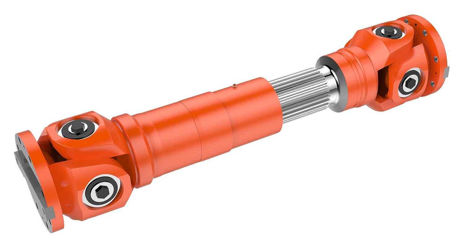
A cardan shaft system, also known as a propeller shaft or drive shaft, consists of several components that work together to transmit torque and rotational power between non-aligned components. The structure of a cardan shaft system typically includes the following components:
1. Shaft Tubes:
– The shaft tubes are the main structural elements of a cardan shaft system. They are cylindrical tubes made of durable and high-strength materials such as steel or aluminum alloy. The shaft tubes provide the backbone of the system and are responsible for transmitting torque and rotational power. They are designed to withstand high loads and torsional forces without deformation or failure.
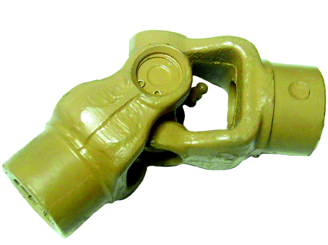
2. Universal Joints:
– Universal joints, also known as U-joints or Cardan joints, are crucial components of a cardan shaft system. They are used to connect and articulate the shaft tubes, allowing for angular misalignment between the driving and driven components. Universal joints consist of a cross-shaped yoke with needle bearings at each end. The yoke connects the shaft tubes, while the needle bearings enable the rotational motion and flexibility required for misalignment compensation. Universal joints allow the cardan shaft system to transmit torque even when the driving and driven components are not perfectly aligned.
3. Slip Yokes:
– Slip yokes are components used in cardan shaft systems that can accommodate axial misalignment. They are typically located at one or both ends of the shaft tubes and provide a sliding connection between the shaft and the driving or driven component. Slip yokes allow the shaft to adjust its length and compensate for changes in the distance between the components. This feature is particularly useful in applications where the distance between the driving and driven components can vary, such as vehicles with adjustable wheelbases or machinery with variable attachment points.
4. Flanges and Yokes:
– Flanges and yokes are used to connect the cardan shaft system to the driving and driven components. Flanges are typically bolted or welded to the ends of the shaft tubes and provide a secure connection point. They have a flange face with bolt holes that align with the corresponding flange on the driving or driven component. Yokes, on the other hand, are cross-shaped components that connect the universal joints to the flanges. They have holes or grooves that accommodate the needle bearings of the universal joints, allowing for rotational motion and torque transfer.
5. Balancing Weights:
– Balancing weights are used to balance the cardan shaft system and minimize vibrations. As the shaft rotates, imbalances in the mass distribution can lead to vibrations, noise, and reduced performance. Balancing weights are strategically placed along the shaft tubes to counterbalance these imbalances. They redistribute the mass, ensuring that the rotational components of the cardan shaft system are properly balanced. Proper balancing improves stability, reduces wear on bearings and other components, and enhances the overall performance and lifespan of the shaft system.
6. Safety Features:
– Some cardan shaft systems incorporate safety features to protect against mechanical failures. For example, protective guards or shielding may be installed to prevent contact with rotating components, reducing the risk of accidents or injuries. In applications where excessive forces or torques can occur, cardan shaft systems may include safety mechanisms such as shear pins or torque limiters. These features are designed to protect the shaft and other components from damage by shearing or disengaging in case of overload or excessive torque.
In summary, a cardan shaft system consists of shaft tubes, universal joints, slip yokes, flanges, and yokes, as well as balancing weights and safety features. These components work together to transmit torque and rotational power between non-aligned components, allowing for angular and axial misalignment compensation. The structure and components of a cardan shaft system are carefully designed to ensure efficient power transmission, flexibility, durability, and safety in various applications.


editor by CX 2024-02-25
China Standard CHINAMFG Drive Worm Gearbox Shaft Input Nrv Series
Product Description
RV series Characteristics
- RV – Sizes:–150
- Input Options: with input shaft, With Square flange,With Input Flange
- Input Power 0.06 to 11 kW
- RV-Size from 030 to 105 in die-cast aluminium alloy budy and over 110 in cast iron
- Ratios between 5 and 100
- Max torque 1550 N.m and admissible output radial loads max 8771 N
- Aluminium units are supplied complete with synthetic oil and allow for universal mounting positions, with no need to modify lubricant quantity
- Worm wheel: Copper (KK Cu).
- Loading capacity in accordance with: ISO 9001:2015/GB/T 19001-2016
- Size 030 and over are painted with RAL 5571 blue
- Worm gear reducers are available with diffferent combinations: NMRV+NMRV, NMRVpower+NMRV, JWB+NMRV
- NMRV, NRV+VS,NMRV+AS,NMRV+VS,NMRV+F
- Options: torque arm, output flange, viton oil seals, low/high temperature oil, filling/drain/breather/level plug,Small gap
Basic models can be applied to a wide range of power reduction ratios from 5 to 1000.
Warranty: One year from date of delivery.
| WORM GEARBOX | |||||
| SNW SERIES | Output Speed Range: | ||||
| Type | Old Type | Output Torque | Output Shaft Dia. | 14rpm-280rpm | |
| SNW030 | RV030 | 21N.m | φ14 | Applicable Motor Power: | |
| SNW040 | RV040 | 45N.m | φ19 | 0.06kW-11kW | |
| SNW050 | RV050 | 84N.m | φ25 | Input Options1: | |
| SNW063 | RV063 | 160N.m | φ25 | With Inline AC Motor | |
| SNW075 | RV075 | 230N.m | φ28 | Input Options2: | |
| SNW090 | RV090 | 410N.m | φ35 | With Square flange | |
| SNW105 | RV105 | 630N.m | φ42 | Input Options3: | |
| SNW110 | RV110 | 725N.m | φ42 | With Input Shaft | |
| SNW130 | RV130 | 1050N.m | φ45 | Input Options4: | |
| SNW150 | RV150 | 1550N.m | φ50 | With Input Flange |
Starshine Drive
ZheJiang CZPT Drive Co.,Ltd,the predecessor was a state-owned military mould enterprise, was established in 1965. CZPT specializes in the complete power transmission solution for high-end equipment manufacturing industries based on the aim of “Platform Product, Application Design and Professional Service”.
Starshine have a strong technical force with over 350 employees at present, including over 30 engineering technicians, 30 quality inspectors, covering an area of 80000 square CZPT and kinds of advanced processing machines and testing equipments. We have a good foundation for the industry application development and service of high-end speed reducers & variators owning to the provincial engineering technology research center,the lab of gear speed reducers, and the base of modern R&D.
Our Team
Quality Control
Quality:Insist on Improvement,Strive for Excellence With the development of equipment manufacturing indurstry,customer never satirsfy with the current quality of our products,on the contrary,wcreate the value of quality.
Quality policy:to enhance the overall level in the field of power transmission
Quality View:Continuous Improvement , pursuit of excellence
Quality Philosophy:Quality creates value
3. Incoming Quality Control
To establish the AQL acceptable level of incoming material control, to provide the material for the whole inspection, sampling, immunity. On the acceptance of qualified products to warehousing, substandard goods to take return, check, rework, rework inspection; responsible for tracking bad, to monitor the supplier to take corrective measures
to prevent recurrence.
4. Process Quality Control
The manufacturing site of the first examination, inspection and final inspection, sampling according to the requirements of some projects, judging the quality change trend;
found abnormal phenomenon of manufacturing, and supervise the production department to improve, eliminate the abnormal phenomenon or state.
5. FQC(Final QC)
After the manufacturing department will complete the product, stand in the customer’s position on the finished product quality verification, in order to ensure the quality of
customer expectations and needs.
6. OQC(Outgoing QC)
After the product sample inspection to determine the qualified, allowing storage, but when the finished product from the warehouse before the formal delivery of the goods, there is a check, this is called the shipment inspection.Check content:In the warehouse storage and transfer status to confirm, while confirming the delivery of the product
is a product inspection to determine the qualified products.
Packing
Delivery
| Application: | Motor, Machinery, Industry |
|---|---|
| Function: | Distribution Power, Change Drive Torque, Speed Changing, Speed Reduction |
| Layout: | Vertical |
| Hardness: | Hardened |
| Installation: | Torque |
| Step: | Three-Step |
| Customization: |
Available
| Customized Request |
|---|

Are there any limitations or disadvantages associated with drive shafts?
While drive shafts are widely used and offer several advantages, they also have certain limitations and disadvantages that should be considered. Here’s a detailed explanation of the limitations and disadvantages associated with drive shafts:
1. Length and Misalignment Constraints:
Drive shafts have a maximum practical length due to factors such as material strength, weight considerations, and the need to maintain rigidity and minimize vibrations. Longer drive shafts can be prone to increased bending and torsional deflection, leading to reduced efficiency and potential driveline vibrations. Additionally, drive shafts require proper alignment between the driving and driven components. Misalignment can cause increased wear, vibrations, and premature failure of the drive shaft or its associated components.
2. Limited Operating Angles:
Drive shafts, especially those using U-joints, have limitations on operating angles. U-joints are typically designed to operate within specific angular ranges, and operating beyond these limits can result in reduced efficiency, increased vibrations, and accelerated wear. In applications requiring large operating angles, constant velocity (CV) joints are often used to maintain a constant speed and accommodate greater angles. However, CV joints may introduce higher complexity and cost compared to U-joints.
3. Maintenance Requirements:
Drive shafts require regular maintenance to ensure optimal performance and reliability. This includes periodic inspection, lubrication of joints, and balancing if necessary. Failure to perform routine maintenance can lead to increased wear, vibrations, and potential driveline issues. Maintenance requirements should be considered in terms of time and resources when using drive shafts in various applications.
4. Noise and Vibration:
Drive shafts can generate noise and vibrations, especially at high speeds or when operating at certain resonant frequencies. Imbalances, misalignment, worn joints, or other factors can contribute to increased noise and vibrations. These vibrations may affect the comfort of vehicle occupants, contribute to component fatigue, and require additional measures such as dampers or vibration isolation systems to mitigate their effects.
5. Weight and Space Constraints:
Drive shafts add weight to the overall system, which can be a consideration in weight-sensitive applications, such as automotive or aerospace industries. Additionally, drive shafts require physical space for installation. In compact or tightly packaged equipment or vehicles, accommodating the necessary drive shaft length and clearances can be challenging, requiring careful design and integration considerations.
6. Cost Considerations:
Drive shafts, depending on their design, materials, and manufacturing processes, can involve significant costs. Customized or specialized drive shafts tailored to specific equipment requirements may incur higher expenses. Additionally, incorporating advanced joint configurations, such as CV joints, can add complexity and cost to the drive shaft system.
7. Inherent Power Loss:
Drive shafts transmit power from the driving source to the driven components, but they also introduce some inherent power loss due to friction, bending, and other factors. This power loss can reduce overall system efficiency, particularly in long drive shafts or applications with high torque requirements. It is important to consider power loss when determining the appropriate drive shaft design and specifications.
8. Limited Torque Capacity:
While drive shafts can handle a wide range of torque loads, there are limits to their torque capacity. Exceeding the maximum torque capacity of a drive shaft can lead to premature failure, resulting in downtime and potential damage to other driveline components. It is crucial to select a drive shaft with sufficient torque capacity for the intended application.
Despite these limitations and disadvantages, drive shafts remain a widely used and effective means of power transmission in various industries. Manufacturers continuously work to address these limitations through advancements in materials, design techniques, joint configurations, and balancing processes. By carefully considering the specific application requirements and potential drawbacks, engineers and designers can mitigate the limitations and maximize the benefits of drive shafts in their respective systems.

How do drive shafts handle variations in load and vibration during operation?
Drive shafts are designed to handle variations in load and vibration during operation by employing various mechanisms and features. These mechanisms help ensure smooth power transmission, minimize vibrations, and maintain the structural integrity of the drive shaft. Here’s a detailed explanation of how drive shafts handle load and vibration variations:
1. Material Selection and Design:
Drive shafts are typically made from materials with high strength and stiffness, such as steel alloys or composite materials. The material selection and design take into account the anticipated loads and operating conditions of the application. By using appropriate materials and optimizing the design, drive shafts can withstand the expected variations in load without experiencing excessive deflection or deformation.
2. Torque Capacity:
Drive shafts are designed with a specific torque capacity that corresponds to the expected loads. The torque capacity takes into account factors such as the power output of the driving source and the torque requirements of the driven components. By selecting a drive shaft with sufficient torque capacity, variations in load can be accommodated without exceeding the drive shaft’s limits and risking failure or damage.
3. Dynamic Balancing:
During the manufacturing process, drive shafts can undergo dynamic balancing. Imbalances in the drive shaft can result in vibrations during operation. Through the balancing process, weights are strategically added or removed to ensure that the drive shaft spins evenly and minimizes vibrations. Dynamic balancing helps to mitigate the effects of load variations and reduces the potential for excessive vibrations in the drive shaft.
4. Dampers and Vibration Control:
Drive shafts can incorporate dampers or vibration control mechanisms to further minimize vibrations. These devices are typically designed to absorb or dissipate vibrations that may arise from load variations or other factors. Dampers can be in the form of torsional dampers, rubber isolators, or other vibration-absorbing elements strategically placed along the drive shaft. By managing and attenuating vibrations, drive shafts ensure smooth operation and enhance overall system performance.
5. CV Joints:
Constant Velocity (CV) joints are often used in drive shafts to accommodate variations in operating angles and to maintain a constant speed. CV joints allow the drive shaft to transmit power even when the driving and driven components are at different angles. By accommodating variations in operating angles, CV joints help minimize the impact of load variations and reduce potential vibrations that may arise from changes in the driveline geometry.
6. Lubrication and Maintenance:
Proper lubrication and regular maintenance are essential for drive shafts to handle load and vibration variations effectively. Lubrication helps reduce friction between moving parts, minimizing wear and heat generation. Regular maintenance, including inspection and lubrication of joints, ensures that the drive shaft remains in optimal condition, reducing the risk of failure or performance degradation due to load variations.
7. Structural Rigidity:
Drive shafts are designed to have sufficient structural rigidity to resist bending and torsional forces. This rigidity helps maintain the integrity of the drive shaft when subjected to load variations. By minimizing deflection and maintaining structural integrity, the drive shaft can effectively transmit power and handle variations in load without compromising performance or introducing excessive vibrations.
8. Control Systems and Feedback:
In some applications, drive shafts may be equipped with control systems that actively monitor and adjust parameters such as torque, speed, and vibration. These control systems use sensors and feedback mechanisms to detect variations in load or vibrations and make real-time adjustments to optimize performance. By actively managing load variations and vibrations, drive shafts can adapt to changing operating conditions and maintain smooth operation.
In summary, drive shafts handle variations in load and vibration during operation through careful material selection and design, torque capacity considerations, dynamic balancing, integration of dampers and vibration control mechanisms, utilization of CV joints, proper lubrication and maintenance, structural rigidity, and, in some cases, control systems and feedback mechanisms. By incorporating these features and mechanisms, drive shafts ensure reliable and efficient power transmission while minimizing the impact of load variations and vibrations on overall system performance.

Can you explain the different types of drive shafts and their specific applications?
Drive shafts come in various types, each designed to suit specific applications and requirements. The choice of drive shaft depends on factors such as the type of vehicle or equipment, power transmission needs, space limitations, and operating conditions. Here’s an explanation of the different types of drive shafts and their specific applications:
1. Solid Shaft:
A solid shaft, also known as a one-piece or solid-steel drive shaft, is a single, uninterrupted shaft that runs from the engine or power source to the driven components. It is a simple and robust design used in many applications. Solid shafts are commonly found in rear-wheel-drive vehicles, where they transmit power from the transmission to the rear axle. They are also used in industrial machinery, such as pumps, generators, and conveyors, where a straight and rigid power transmission is required.
2. Tubular Shaft:
Tubular shafts, also called hollow shafts, are drive shafts with a cylindrical tube-like structure. They are constructed with a hollow core and are typically lighter than solid shafts. Tubular shafts offer benefits such as reduced weight, improved torsional stiffness, and better damping of vibrations. They find applications in various vehicles, including cars, trucks, and motorcycles, as well as in industrial equipment and machinery. Tubular drive shafts are commonly used in front-wheel-drive vehicles, where they connect the transmission to the front wheels.
3. Constant Velocity (CV) Shaft:
Constant Velocity (CV) shafts are specifically designed to handle angular movement and maintain a constant velocity between the engine/transmission and the driven components. They incorporate CV joints at both ends, which allow flexibility and compensation for changes in angle. CV shafts are commonly used in front-wheel-drive and all-wheel-drive vehicles, as well as in off-road vehicles and certain heavy machinery. The CV joints enable smooth power transmission even when the wheels are turned or the suspension moves, reducing vibrations and improving overall performance.
4. Slip Joint Shaft:
Slip joint shafts, also known as telescopic shafts, consist of two or more tubular sections that can slide in and out of each other. This design allows for length adjustment, accommodating changes in distance between the engine/transmission and the driven components. Slip joint shafts are commonly used in vehicles with long wheelbases or adjustable suspension systems, such as some trucks, buses, and recreational vehicles. By providing flexibility in length, slip joint shafts ensure a constant power transfer, even when the vehicle chassis experiences movement or changes in suspension geometry.
5. Double Cardan Shaft:
A double Cardan shaft, also referred to as a double universal joint shaft, is a type of drive shaft that incorporates two universal joints. This configuration helps to reduce vibrations and minimize the operating angles of the joints, resulting in smoother power transmission. Double Cardan shafts are commonly used in heavy-duty applications, such as trucks, off-road vehicles, and agricultural machinery. They are particularly suitable for applications with high torque requirements and large operating angles, providing enhanced durability and performance.
6. Composite Shaft:
Composite shafts are made from composite materials such as carbon fiber or fiberglass, offering advantages such as reduced weight, improved strength, and resistance to corrosion. Composite drive shafts are increasingly being used in high-performance vehicles, sports cars, and racing applications, where weight reduction and enhanced power-to-weight ratio are critical. The composite construction allows for precise tuning of stiffness and damping characteristics, resulting in improved vehicle dynamics and drivetrain efficiency.
7. PTO Shaft:
Power Take-Off (PTO) shafts are specialized drive shafts used in agricultural machinery and certain industrial equipment. They are designed to transfer power from the engine or power source to various attachments, such as mowers, balers, or pumps. PTO shafts typically have a splined connection at one end to connect to the power source and a universal joint at the other end to accommodate angular movement. They are characterized by their ability to transmit high torque levels and their compatibility with a range of driven implements.
8. Marine Shaft:
Marine shafts, also known as propeller shafts or tail shafts, are specifically designed for marine vessels. They transmit power from the engine to the propeller, enabling propulsion. Marine shafts are usually long and operate in a harsh environment, exposed to water, corrosion, and high torque loads. They are typically made of stainless steel or other corrosion-resistant materials and are designed to withstand the challenging conditions encountered in marine applications.
It’simportant to note that the specific applications of drive shafts may vary depending on the vehicle or equipment manufacturer, as well as the specific design and engineering requirements. The examples provided above highlight common applications for each type of drive shaft, but there may be additional variations and specialized designs based on specific industry needs and technological advancements.
editor by CX 2023-11-18
China 12V DC Worm High Torque Self-locking Reversed Mini Turbine Geared Motor for DIY Robot Rotating Table Door Lock Curtain Machine custom drive shaft shop
Error:获取session失败,

Driveshaft structure and vibrations associated with it
The structure of the drive shaft is critical to its efficiency and reliability. Drive shafts typically contain claw couplings, rag joints and universal joints. Other drive shafts have prismatic or splined joints. Learn about the different types of drive shafts and how they work. If you want to know the vibrations associated with them, read on. But first, let’s define what a driveshaft is.
transmission shaft
As the demand on our vehicles continues to increase, so does the demand on our drive systems. Higher CO2 emission standards and stricter emission standards increase the stress on the drive system while improving comfort and shortening the turning radius. These and other negative effects can place significant stress and wear on components, which can lead to driveshaft failure and increase vehicle safety risks. Therefore, the drive shaft must be inspected and replaced regularly.
Depending on your model, you may only need to replace one driveshaft. However, the cost to replace both driveshafts ranges from $650 to $1850. Additionally, you may incur labor costs ranging from $140 to $250. The labor price will depend on your car model and its drivetrain type. In general, however, the cost of replacing a driveshaft ranges from $470 to $1850.
Regionally, the automotive driveshaft market can be divided into four major markets: North America, Europe, Asia Pacific, and Rest of the World. North America is expected to dominate the market, while Europe and Asia Pacific are expected to grow the fastest. Furthermore, the market is expected to grow at the highest rate in the future, driven by economic growth in the Asia Pacific region. Furthermore, most of the vehicles sold globally are produced in these regions.
The most important feature of the driveshaft is to transfer the power of the engine to useful work. Drive shafts are also known as propeller shafts and cardan shafts. In a vehicle, a propshaft transfers torque from the engine, transmission, and differential to the front or rear wheels, or both. Due to the complexity of driveshaft assemblies, they are critical to vehicle safety. In addition to transmitting torque from the engine, they must also compensate for deflection, angular changes and length changes.
type
Different types of drive shafts include helical shafts, gear shafts, worm shafts, planetary shafts and synchronous shafts. Radial protruding pins on the head provide a rotationally secure connection. At least one bearing has a groove extending along its circumferential length that allows the pin to pass through the bearing. There can also be two flanges on each end of the shaft. Depending on the application, the shaft can be installed in the most convenient location to function.
Propeller shafts are usually made of high-quality steel with high specific strength and modulus. However, they can also be made from advanced composite materials such as carbon fiber, Kevlar and fiberglass. Another type of propeller shaft is made of thermoplastic polyamide, which is stiff and has a high strength-to-weight ratio. Both drive shafts and screw shafts are used to drive cars, ships and motorcycles.
Sliding and tubular yokes are common components of drive shafts. By design, their angles must be equal or intersect to provide the correct angle of operation. Unless the working angles are equal, the shaft vibrates twice per revolution, causing torsional vibrations. The best way to avoid this is to make sure the two yokes are properly aligned. Crucially, these components have the same working angle to ensure smooth power flow.
The type of drive shaft varies according to the type of motor. Some are geared, while others are non-geared. In some cases, the drive shaft is fixed and the motor can rotate and steer. Alternatively, a flexible shaft can be used to control the speed and direction of the drive. In some applications where linear power transmission is not possible, flexible shafts are a useful option. For example, flexible shafts can be used in portable devices.
put up
The construction of the drive shaft has many advantages over bare metal. A shaft that is flexible in multiple directions is easier to maintain than a shaft that is rigid in other directions. The shaft body and coupling flange can be made of different materials, and the flange can be made of a different material than the main shaft body. For example, the coupling flange can be made of steel. The main shaft body is preferably flared on at least one end, and the at least one coupling flange includes a first generally frustoconical projection extending into the flared end of the main shaft body.
The normal stiffness of fiber-based shafts is achieved by the orientation of parallel fibers along the length of the shaft. However, the bending stiffness of this shaft is reduced due to the change in fiber orientation. Since the fibers continue to travel in the same direction from the first end to the second end, the reinforcement that increases the torsional stiffness of the shaft is not affected. In contrast, a fiber-based shaft is also flexible because it uses ribs that are approximately 90 degrees from the centerline of the shaft.
In addition to the helical ribs, the drive shaft 100 may also contain reinforcing elements. These reinforcing elements maintain the structural integrity of the shaft. These reinforcing elements are called helical ribs. They have ribs on both the outer and inner surfaces. This is to prevent shaft breakage. These elements can also be shaped to be flexible enough to accommodate some of the forces generated by the drive. Shafts can be designed using these methods and made into worm-like drive shafts.
vibration
The most common cause of drive shaft vibration is improper installation. There are five common types of driveshaft vibration, each related to installation parameters. To prevent this from happening, you should understand what causes these vibrations and how to fix them. The most common types of vibration are listed below. This article describes some common drive shaft vibration solutions. It may also be beneficial to consider the advice of a professional vibration technician for drive shaft vibration control.
If you’re not sure if the problem is the driveshaft or the engine, try turning on the stereo. Thicker carpet kits can also mask vibrations. Nonetheless, you should contact an expert as soon as possible. If vibration persists after vibration-related repairs, the driveshaft needs to be replaced. If the driveshaft is still under warranty, you can repair it yourself.
CV joints are the most common cause of third-order driveshaft vibration. If they are binding or fail, they need to be replaced. Alternatively, your CV joints may just be misaligned. If it is loose, you can check the CV connector. Another common cause of drive shaft vibration is improper assembly. Improper alignment of the yokes on both ends of the shaft can cause them to vibrate.
Incorrect trim height can also cause driveshaft vibration. Correct trim height is necessary to prevent drive shaft wobble. Whether your vehicle is new or old, you can perform some basic fixes to minimize problems. One of these solutions involves balancing the drive shaft. First, use the hose clamps to attach the weights to it. Next, attach an ounce of weight to it and spin it. By doing this, you minimize the frequency of vibration.
cost
The global driveshaft market is expected to exceed (xxx) million USD by 2028, growing at a compound annual growth rate (CAGR) of XX%. Its soaring growth can be attributed to several factors, including increasing urbanization and R&D investments by leading market players. The report also includes an in-depth analysis of key market trends and their impact on the industry. Additionally, the report provides a comprehensive regional analysis of the Driveshaft Market.
The cost of replacing the drive shaft depends on the type of repair required and the cause of the failure. Typical repair costs range from $300 to $750. Rear-wheel drive cars usually cost more. But front-wheel drive vehicles cost less than four-wheel drive vehicles. You may also choose to try repairing the driveshaft yourself. However, it is important to do your research and make sure you have the necessary tools and equipment to perform the job properly.
The report also covers the competitive landscape of the Drive Shafts market. It includes graphical representations, detailed statistics, management policies, and governance components. Additionally, it includes a detailed cost analysis. Additionally, the report presents views on the COVID-19 market and future trends. The report also provides valuable information to help you decide how to compete in your industry. When you buy a report like this, you are adding credibility to your work.
A quality driveshaft can improve your game by ensuring distance from the tee and improving responsiveness. The new material in the shaft construction is lighter, stronger and more responsive than ever before, so it is becoming a key part of the driver. And there are a variety of options to suit any budget. The main factor to consider when buying a shaft is its quality. However, it’s important to note that quality doesn’t come cheap and you should always choose an axle based on what your budget can handle.
editor by Cx 2023-04-26
China Worm Wheel Main Drive Shaft Bevel Gear drive shaft shop
Item Description
CZPT Digital Manufacturing unit can be source the gears according to the drawings, samples and materials supplied by the consumers.
Straight teeth gear, helical tooth gear, spiral bevel gear, bevel wheel, nylon gear, bevel gear and so forth.
Substance as clients ask for.
Alloy steel, carbon and stainless steel, Brass, Copper and Aluminum, Nylon
Forging and casting. Bevel Gear Straight Bevel Equipment Worm Gear Spur Gear Forging Bevel Gears Sprocket Push Sprocket Sprocket Galvanized Sprocket Motorbike Chain Sprocket Ybr125 Sprocket
Competitive Costs,Best quality ,Prompt Delivery and Greatest Service Confident!
Aggressive Benefits
Well and Large Top quality Handle,
Prompt Delivery,
Competitive Charges,
Modest Purchase Suitable,
ODM Accepted,
OEM Accepted.
Fore more info ,please make contact with us in time.
| Application: | Motor, Electric Cars, Motorcycle, Machinery, Marine, Toy, Agricultural Machinery, Car |
|---|---|
| Hardness: | Hardened Tooth Surface |
| Gear Position: | External Gear |
| Manufacturing Method: | Sintered Gear |
| Toothed Portion Shape: | Bevel Wheel |
| Material: | Stainless Steel |
###
| Customization: |
Available
|
|---|
Guide to Drive Shafts and U-Joints
If you’re concerned about the performance of your car’s driveshaft, you’re not alone. Many car owners are unaware of the warning signs of a failed driveshaft, but knowing what to look for can help you avoid costly repairs. Here is a brief guide on drive shafts, U-joints and maintenance intervals. Listed below are key points to consider before replacing a vehicle driveshaft.
Symptoms of Driveshaft Failure
Identifying a faulty driveshaft is easy if you’ve ever heard a strange noise from under your car. These sounds are caused by worn U-joints and bearings supporting the drive shaft. When they fail, the drive shafts stop rotating properly, creating a clanking or squeaking sound. When this happens, you may hear noise from the side of the steering wheel or floor.
In addition to noise, a faulty driveshaft can cause your car to swerve in tight corners. It can also lead to suspended bindings that limit overall control. Therefore, you should have these symptoms checked by a mechanic as soon as you notice them. If you notice any of the symptoms above, your next step should be to tow your vehicle to a mechanic. To avoid extra trouble, make sure you’ve taken precautions by checking your car’s oil level.
In addition to these symptoms, you should also look for any noise from the drive shaft. The first thing to look for is the squeak. This was caused by severe damage to the U-joint attached to the drive shaft. In addition to noise, you should also look for rust on the bearing cap seals. In extreme cases, your car can even shudder when accelerating.
Vibration while driving can be an early warning sign of a driveshaft failure. Vibration can be due to worn bushings, stuck sliding yokes, or even springs or bent yokes. Excessive torque can be caused by a worn center bearing or a damaged U-joint. The vehicle may make unusual noises in the chassis system.
If you notice these signs, it’s time to take your car to a mechanic. You should check regularly, especially heavy vehicles. If you’re not sure what’s causing the noise, check your car’s transmission, engine, and rear differential. If you suspect that a driveshaft needs to be replaced, a certified mechanic can replace the driveshaft in your car.
Drive shaft type
Driveshafts are used in many different types of vehicles. These include four-wheel drive, front-engine rear-wheel drive, motorcycles and boats. Each type of drive shaft has its own purpose. Below is an overview of the three most common types of drive shafts:
The driveshaft is a circular, elongated shaft that transmits torque from the engine to the wheels. Drive shafts often contain many joints to compensate for changes in length or angle. Some drive shafts also include connecting shafts and internal constant velocity joints. Some also include torsional dampers, spline joints, and even prismatic joints. The most important thing about the driveshaft is that it plays a vital role in transmitting torque from the engine to the wheels.
The drive shaft needs to be both light and strong to move torque. While steel is the most commonly used material for automotive driveshafts, other materials such as aluminum, composites, and carbon fiber are also commonly used. It all depends on the purpose and size of the vehicle. Precision Manufacturing is a good source for OEM products and OEM driveshafts. So when you’re looking for a new driveshaft, keep these factors in mind when buying.
Cardan joints are another common drive shaft. A universal joint, also known as a U-joint, is a flexible coupling that allows one shaft to drive the other at an angle. This type of drive shaft allows power to be transmitted while the angle of the other shaft is constantly changing. While a gimbal is a good option, it’s not a perfect solution for all applications.
CZPT, Inc. has state-of-the-art machinery to service all types of drive shafts, from small cars to race cars. They serve a variety of needs, including racing, industry and agriculture. Whether you need a new drive shaft or a simple adjustment, the staff at CZPT can meet all your needs. You’ll be back on the road soon!
U-joint
If your car yoke or u-joint shows signs of wear, it’s time to replace them. The easiest way to replace them is to follow the steps below. Use a large flathead screwdriver to test. If you feel any movement, the U-joint is faulty. Also, inspect the bearing caps for damage or rust. If you can’t find the u-joint wrench, try checking with a flashlight.
When inspecting U-joints, make sure they are properly lubricated and lubricated. If the joint is dry or poorly lubricated, it can quickly fail and cause your car to squeak while driving. Another sign that a joint is about to fail is a sudden, excessive whine. Check your u-joints every year or so to make sure they are in proper working order.
Whether your u-joint is sealed or lubricated will depend on the make and model of your vehicle. When your vehicle is off-road, you need to install lubricable U-joints for durability and longevity. A new driveshaft or derailleur will cost more than a U-joint. Also, if you don’t have a good understanding of how to replace them, you may need to do some transmission work on your vehicle.
When replacing the U-joint on the drive shaft, be sure to choose an OEM replacement whenever possible. While you can easily repair or replace the original head, if the u-joint is not lubricated, you may need to replace it. A damaged gimbal joint can cause problems with your car’s transmission or other critical components. Replacing your car’s U-joint early can ensure its long-term performance.
Another option is to use two CV joints on the drive shaft. Using multiple CV joints on the drive shaft helps you in situations where alignment is difficult or operating angles do not match. This type of driveshaft joint is more expensive and complex than a U-joint. The disadvantages of using multiple CV joints are additional length, weight, and reduced operating angle. There are many reasons to use a U-joint on a drive shaft.
maintenance interval
Checking U-joints and slip joints is a critical part of routine maintenance. Most vehicles are equipped with lube fittings on the driveshaft slip joint, which should be checked and lubricated at every oil change. CZPT technicians are well-versed in axles and can easily identify a bad U-joint based on the sound of acceleration or shifting. If not repaired properly, the drive shaft can fall off, requiring expensive repairs.
Oil filters and oil changes are other parts of a vehicle’s mechanical system. To prevent rust, the oil in these parts must be replaced. The same goes for transmission. Your vehicle’s driveshaft should be inspected at least every 60,000 miles. The vehicle’s transmission and clutch should also be checked for wear. Other components that should be checked include PCV valves, oil lines and connections, spark plugs, tire bearings, steering gearboxes and brakes.
If your vehicle has a manual transmission, it is best to have it serviced by CZPT’s East Lexington experts. These services should be performed every two to four years or every 24,000 miles. For best results, refer to the owner’s manual for recommended maintenance intervals. CZPT technicians are experienced in axles and differentials. Regular maintenance of your drivetrain will keep it in good working order.
editor by czh 2023-01-23
China Hot selling Non Standard Customization Worm gears shaft worm wheel for farm machinery Rotary Tiller with Great quality
Products Description MaterialsTypes of steel, brass, bronze, cast iron, ductile iron, aluminum, powdered metals, and plastics.Steel is the most common materialoverall,CertificationAS 9100D&BS EN ISO 9001:2015Production Capacity200000 pieces per monthLead Time35 daysOur serviceSWISS MACHINING; DEBURRING; 9571-35075 957135075 Oil seal axle case for CZPT corolla yaris C-HR front drive shaft oil seal LATHE/TURNING; 5 Axis; MICROMACHININGApplicationIndustry,Automation,Medical,Motor ,erospace , defense, packaging equipment , food processing machinery and so on If you need to customize, please click here! for CZPT F-150 Ranger CZPT Edge Transit Explorer F-250 F-350 Over 200 Items Propeller Driveshaft Drive Shaft Related Products Company Information FAQ Q:What is the strength of your company?A:We have a engineer team,who have well experienced on products and machine designs.We can help you to solve the problem you meet.Q:How about you quality?A:We have our own prcoessional factory and worker,so believe that our products have advange over our competitors.Q:What is you MOQ?A:Minimum order quality is 1 piece.Q:Could you produce customized product according to your drawing or sample?A:Yes.We have abundant experience in the production of non-standard products. Packing&Shipping Packaging:Chain+Plastic Bag+ Carton+Wooden case( If you have other requirements, we can customized according to customer requirements packaging. )Shipping :1.Most of the standard ones are in stock which we can send in 3-10 days after inspection and package.2. Customized products delivery time should be determined according to the number. Payment Terms We can accept a variety of payment.1) TT, 30% deposit , 70% before shippment.2) L/C at sight. (high bank charge, RV25-185 Speed Worm drive Gear Reducer gearbox with motor not suggest , but acceptable )3) 100% Western Union in advance. (specially for air shipment or small amoun)4) Small order by paypal.
Contact Us
How to Calculate the Diameter of a Worm Gear

In this article, we will discuss the characteristics of the Duplex, Single-throated, and Undercut worm gears and the analysis of worm shaft deflection. Besides that, we will explore how the diameter of a worm gear is calculated. If you have any doubt about the function of a worm gear, you can refer to the table below. Also, keep in mind that a worm gear has several important parameters which determine its working.
Duplex worm gear
A duplex worm gear set is distinguished by its ability to maintain precise angles and high gear ratios. The backlash of the gearing can be readjusted several times. The axial position of the worm shaft can be determined by adjusting screws on the housing cover. This feature allows for low backlash engagement of the worm tooth pitch with the worm gear. This feature is especially beneficial when backlash is a critical factor when selecting gears.
The standard worm gear shaft requires less lubrication than its dual counterpart. Worm gears are difficult to lubricate because they are sliding rather than rotating. They also have fewer moving parts and fewer points of failure. The disadvantage of a worm gear is that you cannot reverse the direction of power due to friction between the worm and the wheel. Because of this, they are best used in machines that operate at low speeds.
Worm wheels have teeth that form a helix. This helix produces axial thrust forces, depending on the hand of the helix and the direction of rotation. To handle these forces, the worms should be mounted securely using dowel pins, step shafts, and dowel pins. To prevent the worm from shifting, the worm wheel axis must be aligned with the center of the worm wheel’s face width.
The backlash of the CZPT duplex worm gear is adjustable. By shifting the worm axially, the section of the worm with the desired tooth thickness is in contact with the wheel. As a result, the backlash is adjustable. Worm gears are an excellent choice for rotary tables, high-precision reversing applications, and ultra-low-backlash gearboxes. Axial shift backlash is a major advantage of duplex worm gears, and this feature translates into a simple and fast assembly process.
When choosing a gear set, the size and lubrication process will be crucial. If you’re not careful, you might end up with a damaged gear or one with improper backlash. Luckily, there are some simple ways to maintain the proper tooth contact and backlash of your worm gears, ensuring long-term reliability and performance. As with any gear set, proper lubrication will ensure your worm gears last for years to come.
Single-throated worm gear
Worm gears mesh by sliding and rolling motions, but sliding contact dominates at high reduction ratios. Worm gears’ efficiency is limited by the friction and heat generated during sliding, so lubrication is necessary to maintain optimal efficiency. The worm and gear are usually made of dissimilar metals, such as phosphor-bronze or hardened steel. MC nylon, a synthetic engineering plastic, is often used for the shaft.
Worm gears are highly efficient in transmission of power and are adaptable to various types of machinery and devices. Their low output speed and high torque make them a popular choice for power transmission. A single-throated worm gear is easy to assemble and lock. A double-throated worm gear requires two shafts, one for each worm gear. Both styles are efficient in high-torque applications.
Worm gears are widely used in power transmission applications because of their low speed and compact design. A numerical model was developed to calculate the quasi-static load sharing between gears and mating surfaces. The influence coefficient method allows fast computing of the deformation of the gear surface and local contact of the mating surfaces. The resultant analysis shows that a single-throated worm gear can reduce the amount of energy required to drive an electric motor.
In addition to the wear caused by friction, a worm wheel can experience additional wear. Because the worm wheel is softer than the worm, most of the wear occurs on the wheel. In fact, the number of teeth on a worm wheel should not match its thread count. A single-throated worm gear shaft can increase the efficiency of a machine by as much as 35%. In addition, it can lower the cost of running.
A worm gear is used when the diametrical pitch of the worm wheel and worm gear are the same. If the diametrical pitch of both gears is the same, the two worms will mesh properly. In addition, the worm wheel and worm will be attached to each other with a set screw. This screw is inserted into the hub and then secured with a locknut.
Undercut worm gear
Undercut worm gears have a cylindrical shaft, and their teeth are shaped in an evolution-like pattern. Worms are made of a hardened cemented metal, 16MnCr5. The number of gear teeth is determined by the pressure angle at the zero gearing correction. The teeth are convex in normal and centre-line sections. The diameter of the worm is determined by the worm’s tangential profile, d1. Undercut worm gears are used when the number of teeth in the cylinder is large, and when the shaft is rigid enough to resist excessive load.
The center-line distance of the worm gears is the distance from the worm centre to the outer diameter. This distance affects the worm’s deflection and its safety. Enter a specific value for the bearing distance. Then, the software proposes a range of suitable solutions based on the number of teeth and the module. The table of solutions contains various options, and the selected variant is transferred to the main calculation.
A pressure-angle-angle-compensated worm can be manufactured using single-pointed lathe tools or end mills. The worm’s diameter and depth are influenced by the cutter used. In addition, the diameter of the grinding wheel determines the profile of the worm. If the worm is cut too deep, it will result in undercutting. Despite the undercutting risk, the design of worm gearing is flexible and allows considerable freedom.
The reduction ratio of a worm gear is massive. With only a little effort, the worm gear can significantly reduce speed and torque. In contrast, conventional gear sets need to make multiple reductions to get the same reduction level. Worm gears also have several disadvantages. Worm gears can’t reverse the direction of power because the friction between the worm and the wheel makes this impossible. The worm gear can’t reverse the direction of power, but the worm moves from one direction to another.
The process of undercutting is closely related to the profile of the worm. The worm’s profile will vary depending on the worm diameter, lead angle, and grinding wheel diameter. The worm’s profile will change if the generating process has removed material from the tooth base. A small undercut reduces tooth strength and reduces contact. For smaller gears, a minimum of 14-1/2degPA gears should be used.
Analysis of worm shaft deflection
To analyze the worm shaft deflection, we first derived its maximum deflection value. The deflection is calculated using the Euler-Bernoulli method and Timoshenko shear deformation. Then, we calculated the moment of inertia and the area of the transverse section using CAD software. In our analysis, we used the results of the test to compare the resulting parameters with the theoretical ones.
We can use the resulting centre-line distance and worm gear tooth profiles to calculate the required worm deflection. Using these values, we can use the worm gear deflection analysis to ensure the correct bearing size and worm gear teeth. Once we have these values, we can transfer them to the main calculation. Then, we can calculate the worm deflection and its safety. Then, we enter the values into the appropriate tables, and the resulting solutions are automatically transferred into the main calculation. However, we have to keep in mind that the deflection value will not be considered safe if it is larger than the worm gear’s outer diameter.
We use a four-stage process for investigating worm shaft deflection. We first apply the finite element method to compute the deflection and compare the simulation results with the experimentally tested worm shafts. Finally, we perform parameter studies with 15 worm gear toothings without considering the shaft geometry. This step is the first of four stages of the investigation. Once we have calculated the deflection, we can use the simulation results to determine the parameters needed to optimize the design.
Using a calculation system to calculate worm shaft deflection, we can determine the efficiency of worm gears. There are several parameters to optimize gearing efficiency, including material and geometry, and lubricant. In addition, we can reduce the bearing losses, which are caused by bearing failures. We can also identify the supporting method for the worm shafts in the options menu. The theoretical section provides further information.


China factory dc 12v double shaft electric dc worm gear box reduction motor with Best Sales
dc 12v double shaft electric dc worm gear box reduction motor
Product name
Reversible dc 12v double shaft electricApplication:
Auto shutter , blinding machine , automatic TV rack, money counter, spot light, tissue machine, office equippments, household appliances, LC Genuine auto parts U20118W10 535012810 F-556174.01 Alternator Pulley for CZPT Ranger Transit automatic actuatorOriginal
HangZhou,Guang dong province,china
Material
stealMOQ
1 piece
Capacity
2000 pieces/daySample
DependsTransportation
air or by shipPayment
T/T,L/C,Western Union,paypal…
Package
carton package by customizationOur Advantages:
1.Ensure the motors meet the quality standards.
2. Ensure the motors will be delivereied on time.
3.Provide warm and friendly service and after-sale service for motors.
4We will reply you within 24 hours.
5Guaranteed the realible quality and service of motor,you will find that imported directly from us is so easy and simple as you buy from local supplier.Best price and more choose.
The clear view of Reversible dc 12v double shaft electric
The specification of worm gear motor can be customized
Reversible dc 12v double shaft electric dimension drawing
Advantage of Reversible dc 12v double shaft electric
This type is miniature Worm Gear DC Motor, which can change shaft rotation direction while the wiring positive and negative be changed. It’ 100 Ton Industrial Hydraulic Puller Manufacturer High Quality and Low Price s also have addition 2 characteristics: 1.With self-locking, the output shaft can’t rotation when switch off, that is self-locking. 2.Gearbox output shaft and motor shaft are come to be a rectangle, it’s widely used in various of occasions that require special install size.
FAQQ1 Access to motor product information.
Internet:RANSI website contains the latest corporate news and product update.
Email:The use of the motor, purchase, and technical inquiries, Auto Transmission Spare Parts Automotive Parts Drive Shafts For BMW X3(E83) 3165719201 2003-2011 welcome to contact.
Q2 Are you the gear motor manufacturer?
Yes. We have our own factory and sales company, passed the onsite check by alibaba.
Q3 What is the main product of your company?
The main products are brushed motor brushless motor and stepped motor with or without gear box, DC/AC gear motor, planetary gear motor, DC micro motor , Stepper motor,
stepper gear motor, linear step motor
Q4 Do you have the best price?Not best price, Drive Shaft Center Support Bearing for CZPT HB88107HB88512 only the right price with right motor.
Q5 Gear motor products can be customized?
Yes, the general situation can be customized. We offer OEM service.
Q6 How do I place an order?
You can email us, or the Credit gurrante of Alibaba online orders. We will discuss and confirm the order details together.
Company Information
Contact us
Worm Shafts and Gearboxes
If you have a gearbox, you may be wondering what the best Worm Shaft is for your application. There are several things to consider, including the Concave shape, Number of threads, and Lubrication. This article will explain each factor and help you choose the right Worm Shaft for your gearbox. There are many options available on the market, so don’t hesitate to shop around. If you are new to the world of gearboxes, read on to learn more about this popular type of gearbox.
Concave shape
The geometry of a worm gear varies considerably depending on its manufacturer and its intended use. Early worms had a basic profile that resembled a screw thread and could be chased on a lathe. Later, tools with a straight sided g-angle were developed to produce threads that were parallel to the worm’s axis. Grinding was also developed to improve the finish of worm threads and minimize distortions that occur with hardening.
To select a worm with the proper geometry, the diameter of the worm gear must be in the same unit as the worm’s shaft. Once the basic profile of the worm gear is determined, the worm gear teeth can be specified. The calculation also involves an angle for the worm shaft to prevent it from overheating. The angle of the worm shaft should be as close to the vertical axis as possible.
Double-enveloping worm gears, on the other hand, do not have a throat around the worm. They are helical gears with a straight worm shaft. Since the teeth of the worm are in contact with each other, they produce significant friction. Unlike double-enveloping worm gears, non-throated worm gears are more compact and can handle smaller loads. They are also easy to manufacture.
The worm gears of different manufacturers offer many advantages. For instance, worm gears are one of the most efficient ways to increase torque, while lower-quality materials like bronze are difficult to lubricate. Worm gears also have a low failure rate because they allow for considerable leeway in the design process. Despite the differences between the two standards, the overall performance of a worm gear system is the same.
The cone-shaped worm is another type. This is a technological scheme that combines a straight worm shaft with a concave arc. The concave arc is also a useful utility model. Worms with this shape have more than three contacts at the same time, which means they can reduce a large diameter without excessive wear. It is also a relatively low-cost model.
Thread pattern
A good worm gear requires a perfect thread pattern. There are a few key parameters that determine how good a thread pattern is. Firstly, the threading pattern must be ACME-threaded. If this is not possible, the thread must be made with straight sides. Then, the linear pitch of the “worm” must be the same as the circular pitch of the corresponding worm wheel. In simple terms, this means the pitch of the “worm” is the same as the circular pitch of the worm wheel. A quick-change gearbox is usually used with this type of worm gear. Alternatively, lead-screw change gears are used instead of a quick-change gear box. The pitch of a worm gear equals the helix angle of a screw.
A worm gear’s axial pitch must match the circular pitch of a gear with a higher axial pitch. The circular pitch is the distance between the points of teeth on the worm, while the axial pitch is the distance between the worm’s teeth. Another factor is the worm’s lead angle. The angle between the pitch cylinder and worm shaft is called its lead angle, and the higher the lead angle, the greater the efficiency of a gear.
Worm gear tooth geometry varies depending on the manufacturer and intended use. In early worms, threading resembled the thread on a screw, and was easily chased using a lathe. Later, grinding improved worm thread finishes and minimized distortions from hardening. As a result, today, most worm gears have a thread pattern corresponding to their size. When selecting a worm gear, make sure to check for the number of threads before purchasing it.
A worm gear’s threading is crucial in its operation. Worm teeth are typically cylindrical, and are arranged in a pattern similar to screw or nut threads. Worm teeth are often formed on an axis of perpendicular compared to their parallel counterparts. Because of this, they have greater torque than their spur gear counterparts. Moreover, the gearing has a low output speed and high torque.
Number of threads
Different types of worm gears use different numbers of threads on their planetary gears. A single threaded worm gear should not be used with a double-threaded worm. A single-threaded worm gear should be used with a single-threaded worm. Single-threaded worms are more effective for speed reduction than double-threaded ones.
The number of threads on a worm’s shaft is a ratio that compares the pitch diameter and number of teeth. In general, worms have 1,2,4 threads, but some have three, five, or six. Counting thread starts can help you determine the number of threads on a worm. A single-threaded worm has fewer threads than a multiple-threaded worm, but a multi-threaded worm will have more threads than a mono-threaded planetary gear.
To measure the number of threads on a worm shaft, a small fixture with two ground faces is used. The worm must be removed from its housing so that the finished thread area can be inspected. After identifying the number of threads, simple measurements of the worm’s outside diameter and thread depth are taken. Once the worm has been accounted for, a cast of the tooth space is made using epoxy material. The casting is moulded between the two tooth flanks. The V-block fixture rests against the outside diameter of the worm.
The circular pitch of a worm and its axial pitch must match the circular pitch of a larger gear. The axial pitch of a worm is the distance between the points of the teeth on a worm’s pitch diameter. The lead of a thread is the distance a thread travels in one revolution. The lead angle is the tangent to the helix of a thread on a cylinder.
The worm gear’s speed transmission ratio is based on the number of threads. A worm gear with a high ratio can be easily reduced in one step by using a set of worm gears. However, a multi-thread worm will have more than two threads. The worm gear is also more efficient than single-threaded gears. And a worm gear with a high ratio will allow the motor to be used in a variety of applications.
Lubrication
The lubrication of a worm gear is particularly challenging, due to its friction and high sliding contact force. Fortunately, there are several options for lubricants, such as compounded oils. Compounded oils are mineral-based lubricants formulated with 10 percent or more fatty acid, rust and oxidation inhibitors, and other additives. This combination results in improved lubricity, reduced friction, and lower sliding wear.
When choosing a lubricant for a worm shaft, make sure the product’s viscosity is right for the type of gearing used. A low viscosity will make the gearbox difficult to actuate and rotate. Worm gears also undergo a greater sliding motion than rolling motion, so grease must be able to migrate evenly throughout the gearbox. Repeated sliding motions will push the grease away from the contact zone.
Another consideration is the backlash of the gears. Worm gears have high gear ratios, sometimes 300:1. This is important for power applications, but is at the same time inefficient. Worm gears can generate heat during the sliding motion, so a high-quality lubricant is essential. This type of lubricant will reduce heat and ensure optimal performance. The following tips will help you choose the right lubricant for your worm gear.
In low-speed applications, a grease lubricant may be sufficient. In higher-speed applications, it’s best to apply a synthetic lubricant to prevent premature failure and tooth wear. In both cases, lubricant choice depends on the tangential and rotational speed. It is important to follow manufacturer’s guidelines regarding the choice of lubricant. But remember that lubricant choice is not an easy task.
China Good quality 120 Cheap Price Can Be Custom Small Worm Gear Shaft Gearbox Motor Speed Reducer with Hot selling
Products Display Specification ModelSeriesReduction ratioRated output torque (Nm)Output maximum torque (Nm)Rated input speed (rpm)120I32304603000423046 0571 0460623046 0571 937 0571 937571032571160320 Enter the maximum speed (rpm)Allowable radial load (N)Allowable Axial Load (N)Maximum radial load (N)Maximum axial load (N)Backlash (arcmin)Moment of inertia≤Φ1460004200560 0571 07800≤55.3420056004.1420056003.6420056003.3420056003.2420056003.14200560571056003 Related Product Company Profile Certifications Why Choose Us Packing And Shipping FAQ Q1: Are you a trading company or manufacturer?A1: We are an experienced manufacturer. Q2: Can I have my own customized product?A2: Yes.OEM& WeiYou Hd700-7 Hd1250-7 Hd1430 Reduction Gearbox Part 1st 2nd 3rd Travel Planetary Carrier Ass’Y Sun Gear Shaft For CZPT ODM are available,including design, logo,package etc. Q3: What’ Wholesale Golf Shaft Adapter Sleeve .335 Tip CZPT made Driver Fairway RH Compatible with M1 M2 M3 M4 M5 M6 SIM SIM2 R15 Drive s the MOQ?A3: For inventory,the MOQ is 1set. Q4: What’s the delivery time?A4: Within 10 days for ready stock order.OEM&ODM order.The exact time depends on actual situation.
Worm Shafts and Gearboxes
If you have a gearbox, you may be wondering what the best Worm Shaft is for your application. There are several things to consider, including the Concave shape, Number of threads, and Lubrication. This article will explain each factor and help you choose the right Worm Shaft for your gearbox. There are many options available on the market, so don’t hesitate to shop around. If you are new to the world of gearboxes, read on to learn more about this popular type of gearbox.
Concave shape
The geometry of a worm gear varies considerably depending on its manufacturer and its intended use. Early worms had a basic profile that resembled a screw thread and could be chased on a lathe. Later, tools with a straight sided g-angle were developed to produce threads that were parallel to the worm’s axis. Grinding was also developed to improve the finish of worm threads and minimize distortions that occur with hardening.
To select a worm with the proper geometry, the diameter of the worm gear must be in the same unit as the worm’s shaft. Once the basic profile of the worm gear is determined, the worm gear teeth can be specified. The calculation also involves an angle for the worm shaft to prevent it from overheating. The angle of the worm shaft should be as close to the vertical axis as possible.
Double-enveloping worm gears, on the other hand, do not have a throat around the worm. They are helical gears with a straight worm shaft. Since the teeth of the worm are in contact with each other, they produce significant friction. Unlike double-enveloping worm gears, non-throated worm gears are more compact and can handle smaller loads. They are also easy to manufacture.
The worm gears of different manufacturers offer many advantages. For instance, worm gears are one of the most efficient ways to increase torque, while lower-quality materials like bronze are difficult to lubricate. Worm gears also have a low failure rate because they allow for considerable leeway in the design process. Despite the differences between the two standards, the overall performance of a worm gear system is the same.
The cone-shaped worm is another type. This is a technological scheme that combines a straight worm shaft with a concave arc. The concave arc is also a useful utility model. Worms with this shape have more than three contacts at the same time, which means they can reduce a large diameter without excessive wear. It is also a relatively low-cost model.
Thread pattern
A good worm gear requires a perfect thread pattern. There are a few key parameters that determine how good a thread pattern is. Firstly, the threading pattern must be ACME-threaded. If this is not possible, the thread must be made with straight sides. Then, the linear pitch of the “worm” must be the same as the circular pitch of the corresponding worm wheel. In simple terms, this means the pitch of the “worm” is the same as the circular pitch of the worm wheel. A quick-change gearbox is usually used with this type of worm gear. Alternatively, lead-screw change gears are used instead of a quick-change gear box. The pitch of a worm gear equals the helix angle of a screw.
A worm gear’s axial pitch must match the circular pitch of a gear with a higher axial pitch. The circular pitch is the distance between the points of teeth on the worm, while the axial pitch is the distance between the worm’s teeth. Another factor is the worm’s lead angle. The angle between the pitch cylinder and worm shaft is called its lead angle, and the higher the lead angle, the greater the efficiency of a gear.
Worm gear tooth geometry varies depending on the manufacturer and intended use. In early worms, threading resembled the thread on a screw, and was easily chased using a lathe. Later, grinding improved worm thread finishes and minimized distortions from hardening. As a result, today, most worm gears have a thread pattern corresponding to their size. When selecting a worm gear, make sure to check for the number of threads before purchasing it.
A worm gear’s threading is crucial in its operation. Worm teeth are typically cylindrical, and are arranged in a pattern similar to screw or nut threads. Worm teeth are often formed on an axis of perpendicular compared to their parallel counterparts. Because of this, they have greater torque than their spur gear counterparts. Moreover, the gearing has a low output speed and high torque.
Number of threads
Different types of worm gears use different numbers of threads on their planetary gears. A single threaded worm gear should not be used with a double-threaded worm. A single-threaded worm gear should be used with a single-threaded worm. Single-threaded worms are more effective for speed reduction than double-threaded ones.
The number of threads on a worm’s shaft is a ratio that compares the pitch diameter and number of teeth. In general, worms have 1,2,4 threads, but some have three, five, or six. Counting thread starts can help you determine the number of threads on a worm. A single-threaded worm has fewer threads than a multiple-threaded worm, but a multi-threaded worm will have more threads than a mono-threaded planetary gear.
To measure the number of threads on a worm shaft, a small fixture with two ground faces is used. The worm must be removed from its housing so that the finished thread area can be inspected. After identifying the number of threads, simple measurements of the worm’s outside diameter and thread depth are taken. Once the worm has been accounted for, a cast of the tooth space is made using epoxy material. The casting is moulded between the two tooth flanks. The V-block fixture rests against the outside diameter of the worm.
The circular pitch of a worm and its axial pitch must match the circular pitch of a larger gear. The axial pitch of a worm is the distance between the points of the teeth on a worm’s pitch diameter. The lead of a thread is the distance a thread travels in one revolution. The lead angle is the tangent to the helix of a thread on a cylinder.
The worm gear’s speed transmission ratio is based on the number of threads. A worm gear with a high ratio can be easily reduced in one step by using a set of worm gears. However, a multi-thread worm will have more than two threads. The worm gear is also more efficient than single-threaded gears. And a worm gear with a high ratio will allow the motor to be used in a variety of applications.
Lubrication
The lubrication of a worm gear is particularly challenging, due to its friction and high sliding contact force. Fortunately, there are several options for lubricants, such as compounded oils. Compounded oils are mineral-based lubricants formulated with 10 percent or more fatty acid, rust and oxidation inhibitors, and other additives. This combination results in improved lubricity, reduced friction, and lower sliding wear.
When choosing a lubricant for a worm shaft, make sure the product’s viscosity is right for the type of gearing used. A low viscosity will make the gearbox difficult to actuate and rotate. Worm gears also undergo a greater sliding motion than rolling motion, so grease must be able to migrate evenly throughout the gearbox. Repeated sliding motions will push the grease away from the contact zone.
Another consideration is the backlash of the gears. Worm gears have high gear ratios, sometimes 300:1. This is important for power applications, but is at the same time inefficient. Worm gears can generate heat during the sliding motion, so a high-quality lubricant is essential. This type of lubricant will reduce heat and ensure optimal performance. The following tips will help you choose the right lubricant for your worm gear.
In low-speed applications, a grease lubricant may be sufficient. In higher-speed applications, it’s best to apply a synthetic lubricant to prevent premature failure and tooth wear. In both cases, lubricant choice depends on the tangential and rotational speed. It is important to follow manufacturer’s guidelines regarding the choice of lubricant. But remember that lubricant choice is not an easy task.
Shaft 6v 250 rpm plastik redüktörlü dc motor manufacturer made in China – replacement parts – in Mar Del Plata Argentina Helical Bevel Reducer Worm Gearbox China Manufacturer Industrial Replacement with top quality

We – EPG Team the greatest worm gearbox, couplings and gears manufacturing facility in China with 5 distinct branches. For far more particulars: Mobile/whatsapp/telegram/Kakao us at: 0086~13083988828 13858117778083988828 /
shaft helical bevel reducer worm gearbox china manufacturer industrial replacement
/ The use of first tools manufacturer’s (OEM) element numbers or emblems , e.g. CASE® and John Deere® are for reference functions only and for indicating product use and compatibility. Our company and the shown alternative components contained herein are not sponsored, authorized, or made by the OEM. /


Nmrv motor manufacturing industry wholesaler made in China – replacement parts – in Hermosillo Mexico Worm Shaft Reduces RV Series Worm Gear Gearboxes with top quality
We – EPG Team the biggest worm gearbox, couplings and gears manufacturing facility in China with 5 various branches. For far more details: Mobile/whatsapp/telegram/Kakao us at: 0086~13083988828 13858117778083988828 /
Technological info listing:
| Kind: | Worm Equipment Speed Reducer |
| Product: | NMRV571–one hundred fifty |
| Ratio: | 1:7.5,10,15,twenty,twenty five,thirty,40,fifty,60,80,a hundred |
| Color: | Blue/Silver Or On Consumer Ask for |
| Content | Housing: Blue-Coloured Forged-Iron Worm Gear-Copper-ten-3# Worm-20CrMn Ti with carburizing and quenching, surface area harness is fifty six-62HRC Shaft-chromium metal-45# |
| Lubricant: | Artificial&Mineral |
| Bearing: | C&U Bearing |
| Seal: | NAK SKF |
| Warranty: | -thirty-40°C |
| ICE FLANGE | 80B5,90B5,100B5,112B5,132B5,160B5 |
| Rated electrical power: | .06KW,.12KW,.25KW,.75KW,1.5KW,3KW,5.5KW,7.5KW |
| Software | Metallurgical equipment, foodstuff machinery, stage machinery, welding machinery, highway equipment, amusement devices, packaging machinery, Rubber and plastic machinery, environmental safety equipment ,engineering machinery, building equipment, machine tool industry, automotive business, logistics and transportation and so on |
| NMRV | PAM | N | M | P | D | |||||||||||
| ICE | 5 | 7.5 | ten | 15 | twenty | twenty five | thirty | forty | fifty | 60 | 80 | 100 | ||||
| 25 | 56B14 | fifty | sixty five | 80 | nine | nine | 9 | nine | 9 | 9 | 9 | nine | nine | |||
| 30 | 63B5 | 95 | a hundred and fifteen | one hundred forty | 11 | 11 | 11 | eleven | eleven | 11 | 11 | 11 | eleven | |||
| 63B14 | 60 | seventy five | 90 | |||||||||||||
| 56B5 | 80 | 100 | a hundred and twenty | nine | 9 | nine | nine | 9 | 9 | 9 | 9 | 9 | 9 | 9 | ||
| 56B14 | 50 | 65 | eighty | |||||||||||||
| 40 | 71B5 | 110 | a hundred thirty | 160 | fourteen | 14 | fourteen | fourteen | 14 | fourteen | 14 | fourteen | ||||
| 71B14 | 70 | 85 | 105 | |||||||||||||
| 63B5 | 95 | 115 | 140 | 11 | 11 | eleven | eleven | eleven | 11 | eleven | eleven | eleven | eleven | 11 | eleven | |
| 63B14 | sixty | seventy five | 90 | |||||||||||||
| 56B5 | eighty | a hundred | a hundred and twenty | 9 | nine | nine | 9 | |||||||||
| 50 | 80B5 | 130 | one hundred sixty five | two hundred | 19 | 19 | 19 | 19 | 19 | 19 | 19 | |||||
| 80B14 | eighty | one hundred | 120 | |||||||||||||
| 71B5 | 110 | one hundred thirty | one hundred sixty | 14 | fourteen | 14 | fourteen | 14 | 14 | 14 | fourteen | fourteen | 14 | fourteen | ||
| 71B14 | 70 | eighty five | a hundred and five | |||||||||||||
| 63B5 | ninety five | 115 | 140 | 11 | eleven | 11 | eleven | eleven | ||||||||
| 63 | 90B5 | one hundred thirty | 165 | 200 | 24 | 24 | 24 | 24 | 24 | 24 | ||||||
| 90B14 | 95 | one hundred fifteen | one hundred forty | |||||||||||||
| 80B5 | a hundred thirty | one hundred sixty five | 200 | 19 | 19 | 19 | 19 | 19 | 19 | 19 | 19 | 19 | ||||
| 80B14 | 80 | a hundred | one hundred twenty | |||||||||||||
| 71B5 | 110 | a hundred thirty | a hundred and sixty | fourteen | fourteen | 14 | fourteen | 14 | ||||||||
| 71B14 | 70 | 85 | one hundred and five | |||||||||||||
| 75 | one hundred/112B5 | a hundred and eighty | 215 | 250 | 28 | 28 | 28 | |||||||||
| a hundred/112B14 | a hundred and ten | a hundred thirty | 150 | |||||||||||||
| 90B5 | one hundred thirty | 165 | 200 | 24 | 24 | 24 | 24 | 24 | 24 | 24 | ||||||
| 90B14 | 95 | 115 | 140 | |||||||||||||
| 80B5 | one hundred thirty | a hundred sixty five | two hundred | 19 | 19 | 19 | 19 | 19 | 19 | 19 | 19 | |||||
| 80B14 | eighty | a hundred | 120 | |||||||||||||
| 71B5 | a hundred and ten | a hundred thirty | one hundred sixty | fourteen | 14 | fourteen | fourteen | |||||||||
| 90 | a hundred/112B5 | a hundred ninety | 215 | 250 | 28 | 28 | 28 | 28 | 28 | 28 | ||||||
| a hundred/112B14 | one hundred ten | 130 | one hundred sixty | |||||||||||||
| 90B5 | 130 | a hundred sixty five | 200 | 24 | 24 | 24 | 24 | 24 | 24 | 24 | 24 | 24 | ||||
| 90B14 | 95 | 115 | a hundred and forty | |||||||||||||
| 80B5 | a hundred thirty | a hundred sixty five | two hundred | 19 | 19 | 19 | 19 | 19 | ||||||||
| 80B14 | eighty | a hundred | 120 | |||||||||||||
| 110 | 132B5 | 230 | 265 | 300 | 38 | 38 | 38 | 38 | ||||||||
| a hundred/112B5 | one hundred eighty | 215 | 250 | 28 | 28 | 28 | 28 | 28 | 28 | 28 | 28 | 28 | ||||
| 90B5 | 130 | a hundred sixty five | 200 | 24 | 24 | 24 | 24 | 24 | 24 | 24 | ||||||
| 80B5 | one hundred thirty | a hundred sixty five | 200 | 19 | 19 | |||||||||||
| 130 | 132B5 | 230 | 265 | 300 | 38 | 38 | 38 | 38 | 38 | 38 | 38 | |||||
| a hundred/112B5 | 180 | 215 | 250 | 28 | 28 | 28 | 28 | 28 | 28 | 28 | ||||||
| 90B5 | one hundred thirty | a hundred sixty five | 200 | 24 | 24 | |||||||||||
| 150 | 160B5 | 250 | three hundred | 350 | 42 | 42 | 42 | forty two | forty two | |||||||
| 132B5 | 230 | 265 | 250 | 38 | 38 | 38 | 38 | 38 | 38 | |||||||
| one hundred/112B5 | one hundred eighty | 215 | 200 | 28 | 28 | 28 | 28 | |||||||||
Workshop display
/ The use of authentic gear manufacturer’s (OEM) part figures or emblems , e.g. CASE® and John Deere® are for reference reasons only and for indicating item use and compatibility. Our company and the shown substitute components contained herein are not sponsored, accredited, or created by the OEM. /
SMR Chinese Factory Wholesaler & Exporter Shaft Mounted worm gear motor reducer

The group is focused on producing all variety of standard roller chains and sprockets, gears & gearboxes, such as conveyor chain & sprockets , stainless steel chain, agricultural chain and has not just sold its products all over china, but also sold more than 65% products to oversees, including Europe, America, South-east Asia, and it also has set up storage logistics in places like Europe.
Overview
Quick Details
- Applicable Industries:
-
Building Material Shops, Manufacturing Plant, Machinery Repair Shops
- Gearing Arrangement:
-
Helical
- Output Torque:
-
max 8000NM
- Input Speed:
-
1440
- Output Speed:
-
72, 110, 288
- Place of Origin:Zhejiang, China
- Brand Name:
-
OEM
- Model Number:
-
SMR
- Rated Power:
-
2.68~134.2
- color of Shaft Mounted speed reducer:
-
green blue gray
Supply Ability
- Supply Ability:
- 500 Piece/Pieces per Month
Packaging & Delivery
- Packaging Details
- standard export packing and wood pallets packing
- Port
- Shanghai or Ningbo
-
Lead Time
: -
Quantity(Boxes) 1 – 500 >500 Est. Time(days) 30 To be negotiated
Online Customization
Product Description
SMR Shaft Mounted worm gear motor reducer
1. Precision High Quality Gearing
Computer designed helical gears, strong alloy materials for high load capacity, ground profile (some intermediate pinions are shaved). Crown tooth profile, in conformance with ISO 1328-1997, 98% efficiency for per stage, smooth quiet operation with several teeth in mesh.
2. Output Hub
*Standard or alternative output hole diameter for choice as follow.
|
ITEM |
Standard output hole diameter |
Alternative output hole ø |
|
B5 |
ø30 |
ø25/35/40 |
|
B13/20 |
ø30 |
ø25/35/40 |
|
C5 |
ø40 |
ø35/45/50 |
|
C13/20 |
ø40 |
ø35/45/50 |
|
D5 |
ø50 |
ø45/55/60/65 |
|
D13/20 |
ø50 |
ø45/55/60/65 |
|
E5 |
ø55 |
ø50/60/65 |
|
E13/20 |
ø55 |
ø50/60/65 |
|
F5 |
ø65 |
ø60/70/75 |
|
F13/20 |
ø65 |
ø60/70/75 |
|
G5 |
ø75 |
ø70/80/85 |
|
G13/20 |
ø75 |
ø70/80/85 |
|
H5 |
ø85 |
ø80/90/95/100 |
|
H13/20 |
ø85 |
ø80/90/95/100 |
|
J5 |
ø100 |
ø90/95/105/110/105120 |
|
J13/20 |
ø100 |
ø90/95/105/110/105120 |
3. Strong Alloy Steel Shafts
Strong alloy steel, hardened, ground on journals, gear seatings and extensions, for maximum torsional loads. Generous size shaft keys for shock loading and conform to ISO standards.
4, Back Stops
Alternative parts, anti-run back device, are available on all 13:1 and 20:1. Ratio units and do not recommend for 5:1.
5. Torque Arm Assembly
For easy adjustment of the belt.
Detailed Images
Related Products
Certifications
Packing & Delivery
Packing Images of SMR Shaft Mounted worm gear motor reducer
Inner Packing: PP bag with carton;
Outer Packing: Wooden case;
Shipment: 20-30 days upon receiving the deposit.
About Us
About Hangzhou Ever-power group(HZPT):
Q: Are you trading company or manufacturer ?
A: HZPT group consists in 3 factories and 2 abroad sales cooperations.we are making vacuum pumps,air compressors and gearboxes.
Q: How long is your delivery time ? What is your terms of payment ?
A: Generally it is 30-45 days. The time may vary depending on the product and the level of customization. For standard products,
the payment is: 30% T/T in advance ,balance before shippment.,for customized products,50% downpayment is requested normally.
Q: What is the exact MOQ or price for your product ?
A: As an OEM company, we can provide and adapt our products to a wide range of needs.Thus, MOQ and price may greatly vary with detail size, material and further specifications;when you place orders,pleasure contact us in advance to communicate all details


