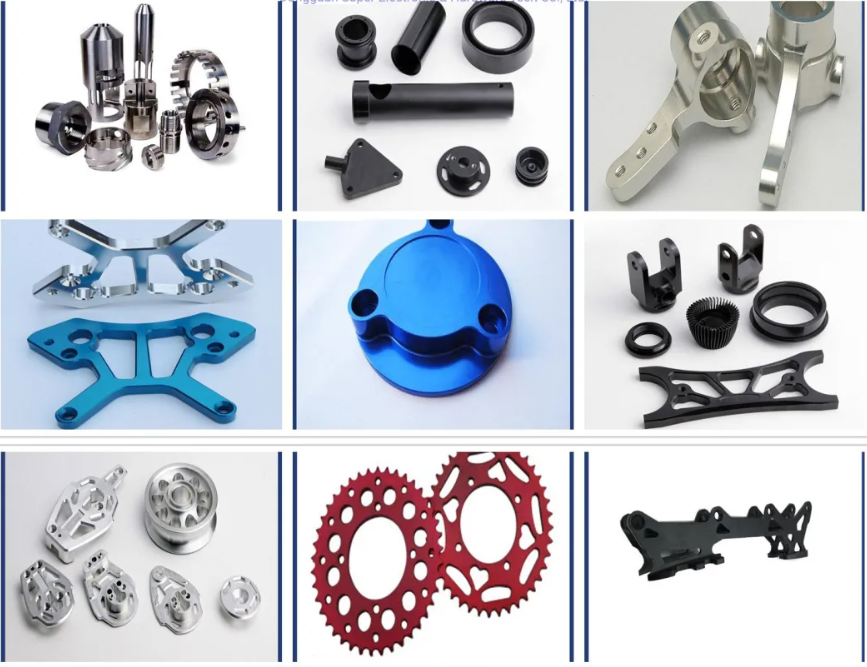
Product Description
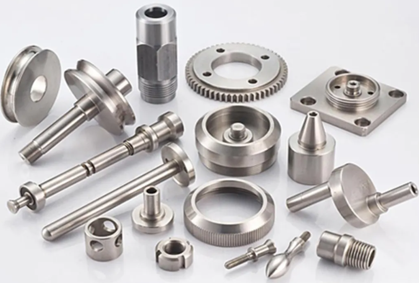
| Product Type | CNC Milling-Turning |
| Our Services | CNC Machining,Plastic Injection,Stamping,Die Casting,Silicone And Rubber,Aluminum Extrusion,Mould Making,etc |
| Material | Aluminum,Brass,Stainless Steel,Copper,Plastic,Wood,Silicone,Rubber,Or as per the customers’ requirements |
| Surface Treatment |
Anodizing,Sandblasting,Painting,Powder coating,Plating,Silk Printing,Brushing,Polishing,Laser Engraving |
| Drawing Format | .jpg/.pdf/.dxf/.dwg/.igs./.stp/x_t. etc |
| Service Project | To provide production design, production and technical service, mould development and processing, etc |
| Testing Machine | Digital Height Gauge, caliper, Coordinate measuring machine, projection machine, roughness tester, hardness tester and so on |
| Tolerance | +/-0.0003mm |
| Packing | Foam, Carton, Wooden boxes, or as per the customer’s requirements |
| Lead Time | 7-20 work days |
| Shipment | By FedEx,DHL,China post… |
| Payment Terms | T/T,Western Union,Paypal |
| Place Of Origin |
ZheJiang ,China(Mainland) |
| Shipment |
Express & air freight is preferred / sea freight/ as per customized specifications |
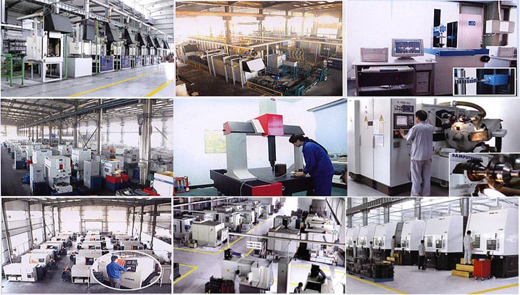
1.Q:Are you trading company or manufacturer?
A: We are factory with more then 15years experience
2.Q: How long is your delivery time?
A: Generally it is 15-30days as we are Customized service we confirm with Customer
when place order
3.Q:Do you provide samples? ls it free or extra?
A: Yes we provide samples .for sample charge as per sample condition to decide free
or charged ,usually for not too much time used consumed machining process are free
4.Q:What is your terms of payment?
30% T/T in advance balance before shipment .Or as per discussion
5.Q: Can we know the production process without visiting the factory?
A:We will offer detailed production schedule and send weekly reports with digital
pictures and videos which show the machining progress
6.Q:Available for customized design drawings?
A: YesDWG.DXF.DXW.IGES.STEP. PDF etc
7.Q:Available for customized design drawings?
A: Yes ,we can CHINAMFG the NDA before your send the drawing
8.Q:How do you guarantee the quality?
A:(1) Checking the raw material after they reach our factory——
Incoming quality control(IQC)
(2) Checking the details before the production line operated
(3) Have a full inspection and routing inspection during mass production—
In-process quality control(IPQC)
(4) Checking the goods after they are finished—- Final quality control(FQC)
(5) Checking the goods after they are finished—–Outgoing quality control(QC)
(6)100% inspection and delivery before shipment.
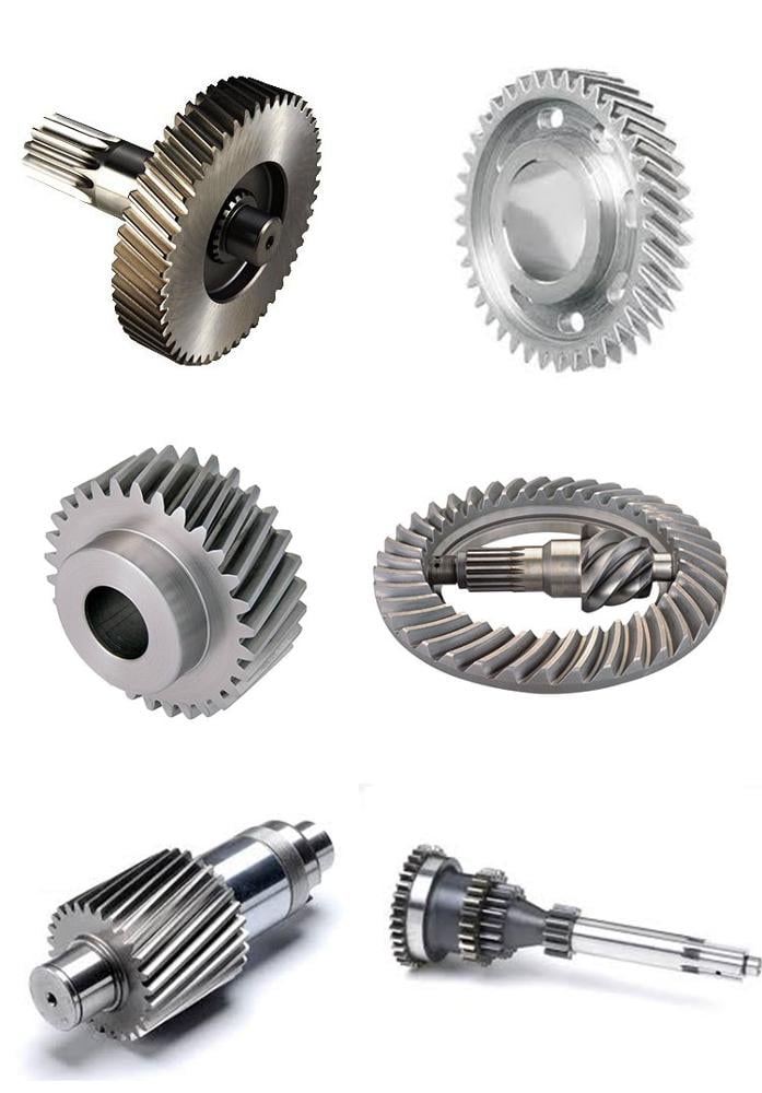
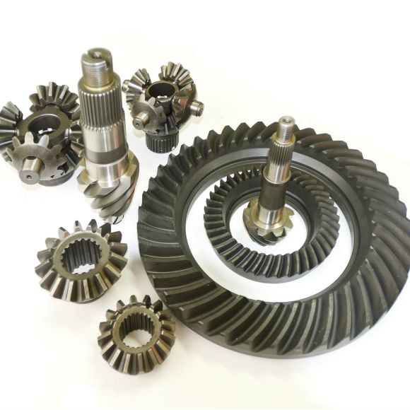
| Gear (Eph-Gear07) &Casting Gear & Helica: | Gear (Eph-Gear07) &Casting Gear & Helical Gears & |
|---|---|
| Transport Package: | Carton or Wooden Box |
| Specification: | Standard |
| Trademark: | EPH |
| Origin: | Qing Dao, Shan Dong, China |
| Customization: |
Available
| Customized Request |
|---|
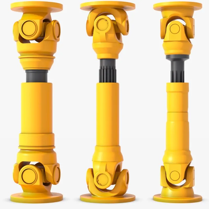
Can cardan shafts be adapted for use in both automotive and industrial settings?
Yes, cardan shafts can be adapted for use in both automotive and industrial settings. They are versatile components that offer efficient power transmission and can be customized to meet the specific requirements of various applications. Let’s explore how cardan shafts can be adapted for both automotive and industrial settings:
1. Automotive Applications:
– Cardan shafts have long been used in automotive applications, especially in vehicles with rear-wheel drive or all-wheel drive systems. They are commonly found in cars, trucks, SUVs, and commercial vehicles. In the automotive sector, cardan shafts are primarily used to transmit torque from the engine or transmission to the differential or axle, allowing power to be distributed to the wheels. They provide a reliable and efficient means of transferring power, even in vehicles that experience varying loads, vibration, and misalignment. Cardan shafts in automotive applications are typically designed to handle specific torque and speed requirements, taking into account factors such as vehicle weight, horsepower, and intended use.
2. Industrial Applications:
– Cardan shafts are also widely used in various industrial settings where torque needs to be transmitted between two rotating components. They are employed in a diverse range of industries, including manufacturing, mining, agriculture, construction, and more. In industrial applications, cardan shafts are utilized in machinery, equipment, and systems that require efficient power transmission over long distances or in situations where angular misalignment is present. Industrial cardan shafts can be customized to accommodate specific torque, speed, and misalignment requirements, considering factors such as the load, rotational speed, operating conditions, and space constraints. They are commonly used in applications such as conveyors, pumps, generators, mixers, crushers, and other industrial machinery.
3. Customization and Adaptability:
– Cardan shafts can be adapted for various automotive and industrial applications through customization. Manufacturers offer a range of cardan shaft options with different lengths, sizes, torque capacities, and speed ratings to suit specific requirements. Universal joints, slip yokes, telescopic sections, and other components can be selected or designed to meet the demands of different settings. Additionally, cardan shafts can be made from different materials, such as steel or aluminum alloy, depending on the application’s needs for strength, durability, or weight reduction. By collaborating with cardan shaft manufacturers and suppliers, automotive and industrial engineers can adapt these components to their specific settings, ensuring optimal performance and reliability.
4. Consideration of Application-Specific Factors:
– When adapting cardan shafts for automotive or industrial settings, it is crucial to consider application-specific factors. These factors may include torque requirements, speed limits, operating conditions (temperature, humidity, etc.), space limitations, and the need for maintenance and serviceability. By carefully evaluating these factors and collaborating with experts, engineers can select or design cardan shafts that meet the unique demands of the automotive or industrial application.
In summary, cardan shafts can be adapted and customized for use in both automotive and industrial settings. Their versatility, efficient power transmission capabilities, and ability to accommodate misalignment make them suitable for a wide range of applications. By considering the specific requirements and collaborating with cardan shaft manufacturers, engineers can ensure that these components provide reliable and efficient power transfer in automotive and industrial systems.
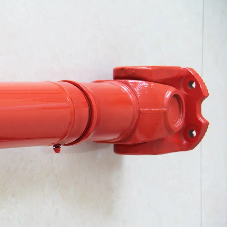
Can you provide real-world examples of vehicles and machinery that use cardan shafts?
Cardan shafts are widely used in various vehicles and machinery across different industries. They are employed in applications where torque transmission, power distribution, and flexibility are crucial. Here are some real-world examples of vehicles and machinery that utilize cardan shafts:
1. Automotive Vehicles:
– Cars, trucks, and SUVs: Cardan shafts are commonly found in rear-wheel drive (RWD) and four-wheel drive (4WD) vehicles. They connect the transmission or transfer case to the rear differential or front differential, respectively, enabling torque transmission to the wheels. Examples include sedans, pickup trucks, and SUVs like Jeep Wrangler, Ford F-150, and Toyota Land Cruiser.
– Buses and commercial vehicles: Cardan shafts are used in buses and commercial vehicles that have rear-wheel drive or all-wheel drive configurations. They transmit torque from the engine or transmission to the rear axle or multiple axles. Examples include city buses, coaches, and delivery trucks.
2. Off-Road and Utility Vehicles:
– Off-road vehicles: Many off-road vehicles, such as off-road trucks, SUVs, and all-terrain vehicles (ATVs) utilize cardan shafts. These shafts provide the necessary torque transfer and power distribution to all wheels for improved traction and off-road capabilities. Examples include the Land Rover Defender, Jeep Wrangler Rubicon, and Yamaha Grizzly ATV.
– Agricultural machinery: Farm equipment like tractors and combine harvesters often employ cardan shafts to transmit power from the engine to various attachments such as mowers, balers, and harvesters. The shafts enable efficient power distribution and flexibility for different agricultural tasks.
– Construction and mining machinery: Equipment used in construction and mining applications, such as excavators, loaders, and bulldozers, utilize cardan shafts to transfer power from the engine or transmission to the different components of the machinery. These shafts enable power distribution and torque transmission to various attachments, allowing for efficient operation in demanding environments.
3. Industrial Machinery:
– Manufacturing machinery: Cardan shafts are used in industrial equipment such as conveyors, mixers, and rotary equipment. They provide torque transmission and power distribution within the machinery, enabling efficient operation and movement of materials.
– Paper and pulp industry: Cardan shafts are employed in paper and pulp processing machinery, including paper machines and pulp digesters. These shafts facilitate power transmission and torque distribution to various parts of the machinery, contributing to smooth operation and high productivity.
– Steel and metal processing machinery: Equipment used in steel mills and metal processing facilities, such as rolling mills, extruders, and coil winding machines, often utilize cardan shafts. These shafts enable power transmission and torque distribution to the different components involved in metal forming, shaping, and processing.
These examples represent just a few of the many applications where cardan shafts are employed. Their versatility, durability, and ability to handle torque transmission and power distribution make them essential components in a wide range of vehicles and machinery across industries.

How do cardan shafts contribute to power transmission and motion in various applications?
Cardan shafts, also known as propeller shafts or drive shafts, play a significant role in power transmission and motion in various applications. They are widely used in automotive, industrial, and marine sectors to transfer torque and rotational power between non-aligned components. Cardan shafts offer several benefits that contribute to efficient power transmission and enable smooth motion in different applications. Here’s a detailed look at how cardan shafts contribute to power transmission and motion:
1. Torque Transmission:
– Cardan shafts are designed to transmit torque from a driving source, such as an engine or motor, to a driven component, such as wheels, propellers, or machinery. They can handle high torque loads and transfer power over long distances. By connecting the driving and driven components, cardan shafts ensure the efficient transmission of rotational power, enabling the motion of vehicles, machinery, or equipment.
2. Angular Misalignment Compensation:
– One of the key advantages of cardan shafts is their ability to accommodate angular misalignment between the driving and driven components. The universal joints present in cardan shafts allow for flexibility and articulation, compensating for variations in the relative positions of the components. This flexibility is crucial in applications where the driving and driven components may not be perfectly aligned, such as vehicles with suspension movement or machinery with adjustable parts. The cardan shaft’s universal joints enable the transmission of torque even when there are angular deviations, ensuring smooth power transfer.
3. Axial Misalignment Compensation:
– In addition to angular misalignment compensation, cardan shafts can also accommodate axial misalignment between the driving and driven components. Axial misalignment refers to the displacement along the axis of the shafts. The design of cardan shafts with telescopic sections or sliding splines allows for axial movement, enabling the shaft to adjust its length to compensate for variations in the distance between the components. This feature is particularly useful in applications where the distance between the driving and driven components can change, such as vehicles with adjustable wheelbases or machinery with variable attachment points.
4. Vibration Damping:
– Cardan shafts contribute to vibration damping in various applications. The flexibility provided by the universal joints helps absorb and dampen vibrations generated during operation. By allowing slight angular deflection and accommodating misalignment, cardan shafts help reduce the transmission of vibrations from the driving source to the driven component. This vibration damping feature improves the overall smoothness of operation, enhances ride comfort in vehicles, and reduces stress on machinery.
5. Balancing:
– To ensure smooth and efficient operation, cardan shafts are carefully balanced. Even minor imbalances in rotational components can result in vibration, noise, and reduced performance. Balancing the cardan shaft minimizes these issues by redistributing mass along the shaft, eliminating or minimizing vibrations caused by centrifugal forces. Proper balancing improves the overall stability, reduces wear on bearings and other components, and extends the lifespan of the shaft and associated equipment.
6. Safety Features:
– Cardan shafts often incorporate safety features to protect against mechanical failures. For example, some cardan shafts have guards or shielding to prevent contact with rotating components, reducing the risk of accidents or injuries. In applications where excessive forces or torques can occur, cardan shafts may include safety mechanisms such as shear pins or torque limiters. These features are designed to protect the shaft and other components from damage by shearing or disengaging in case of overload or excessive torque.
7. Versatility in Applications:
– Cardan shafts offer versatility in their applications. They are widely used in various industries, including automotive, agriculture, mining, marine, and industrial sectors. In automotive applications, cardan shafts transmit power from the engine to the wheels, enabling vehicle propulsion. In industrial machinery, they transfer power between motors and driven components such as conveyors, pumps, or generators. In marine applications, cardan shafts transmit power from the engine to propellers, enabling ship propulsion. The versatility of cardan shafts makes them suitable for a wide range of power transmission needs in different environments.
In summary, cardan shafts are essential components that contribute to efficient power transmission and motion in various applications. Their ability to accommodate angular and axial misalignment, dampen vibrations, balance rotational components, and incorporate safety features enables smooth and reliable operation in vehicles, machinery, and equipment. The versatility of cardan shafts makes them a valuable solution for transmitting torque and rotational power in diverse industries and environments.


editor by CX 2023-12-07
China Good quality 120 Cheap Price Can Be Custom Small Worm Gear Shaft Gearbox Motor Speed Reducer with Hot selling
Products Display Specification ModelSeriesReduction ratioRated output torque (Nm)Output maximum torque (Nm)Rated input speed (rpm)120I32304603000423046 0571 0460623046 0571 937 0571 937571032571160320 Enter the maximum speed (rpm)Allowable radial load (N)Allowable Axial Load (N)Maximum radial load (N)Maximum axial load (N)Backlash (arcmin)Moment of inertia≤Φ1460004200560 0571 07800≤55.3420056004.1420056003.6420056003.3420056003.2420056003.14200560571056003 Related Product Company Profile Certifications Why Choose Us Packing And Shipping FAQ Q1: Are you a trading company or manufacturer?A1: We are an experienced manufacturer. Q2: Can I have my own customized product?A2: Yes.OEM& WeiYou Hd700-7 Hd1250-7 Hd1430 Reduction Gearbox Part 1st 2nd 3rd Travel Planetary Carrier Ass’Y Sun Gear Shaft For CZPT ODM are available,including design, logo,package etc. Q3: What’ Wholesale Golf Shaft Adapter Sleeve .335 Tip CZPT made Driver Fairway RH Compatible with M1 M2 M3 M4 M5 M6 SIM SIM2 R15 Drive s the MOQ?A3: For inventory,the MOQ is 1set. Q4: What’s the delivery time?A4: Within 10 days for ready stock order.OEM&ODM order.The exact time depends on actual situation.
Worm Shafts and Gearboxes
If you have a gearbox, you may be wondering what the best Worm Shaft is for your application. There are several things to consider, including the Concave shape, Number of threads, and Lubrication. This article will explain each factor and help you choose the right Worm Shaft for your gearbox. There are many options available on the market, so don’t hesitate to shop around. If you are new to the world of gearboxes, read on to learn more about this popular type of gearbox.
Concave shape
The geometry of a worm gear varies considerably depending on its manufacturer and its intended use. Early worms had a basic profile that resembled a screw thread and could be chased on a lathe. Later, tools with a straight sided g-angle were developed to produce threads that were parallel to the worm’s axis. Grinding was also developed to improve the finish of worm threads and minimize distortions that occur with hardening.
To select a worm with the proper geometry, the diameter of the worm gear must be in the same unit as the worm’s shaft. Once the basic profile of the worm gear is determined, the worm gear teeth can be specified. The calculation also involves an angle for the worm shaft to prevent it from overheating. The angle of the worm shaft should be as close to the vertical axis as possible.
Double-enveloping worm gears, on the other hand, do not have a throat around the worm. They are helical gears with a straight worm shaft. Since the teeth of the worm are in contact with each other, they produce significant friction. Unlike double-enveloping worm gears, non-throated worm gears are more compact and can handle smaller loads. They are also easy to manufacture.
The worm gears of different manufacturers offer many advantages. For instance, worm gears are one of the most efficient ways to increase torque, while lower-quality materials like bronze are difficult to lubricate. Worm gears also have a low failure rate because they allow for considerable leeway in the design process. Despite the differences between the two standards, the overall performance of a worm gear system is the same.
The cone-shaped worm is another type. This is a technological scheme that combines a straight worm shaft with a concave arc. The concave arc is also a useful utility model. Worms with this shape have more than three contacts at the same time, which means they can reduce a large diameter without excessive wear. It is also a relatively low-cost model.
Thread pattern
A good worm gear requires a perfect thread pattern. There are a few key parameters that determine how good a thread pattern is. Firstly, the threading pattern must be ACME-threaded. If this is not possible, the thread must be made with straight sides. Then, the linear pitch of the “worm” must be the same as the circular pitch of the corresponding worm wheel. In simple terms, this means the pitch of the “worm” is the same as the circular pitch of the worm wheel. A quick-change gearbox is usually used with this type of worm gear. Alternatively, lead-screw change gears are used instead of a quick-change gear box. The pitch of a worm gear equals the helix angle of a screw.
A worm gear’s axial pitch must match the circular pitch of a gear with a higher axial pitch. The circular pitch is the distance between the points of teeth on the worm, while the axial pitch is the distance between the worm’s teeth. Another factor is the worm’s lead angle. The angle between the pitch cylinder and worm shaft is called its lead angle, and the higher the lead angle, the greater the efficiency of a gear.
Worm gear tooth geometry varies depending on the manufacturer and intended use. In early worms, threading resembled the thread on a screw, and was easily chased using a lathe. Later, grinding improved worm thread finishes and minimized distortions from hardening. As a result, today, most worm gears have a thread pattern corresponding to their size. When selecting a worm gear, make sure to check for the number of threads before purchasing it.
A worm gear’s threading is crucial in its operation. Worm teeth are typically cylindrical, and are arranged in a pattern similar to screw or nut threads. Worm teeth are often formed on an axis of perpendicular compared to their parallel counterparts. Because of this, they have greater torque than their spur gear counterparts. Moreover, the gearing has a low output speed and high torque.
Number of threads
Different types of worm gears use different numbers of threads on their planetary gears. A single threaded worm gear should not be used with a double-threaded worm. A single-threaded worm gear should be used with a single-threaded worm. Single-threaded worms are more effective for speed reduction than double-threaded ones.
The number of threads on a worm’s shaft is a ratio that compares the pitch diameter and number of teeth. In general, worms have 1,2,4 threads, but some have three, five, or six. Counting thread starts can help you determine the number of threads on a worm. A single-threaded worm has fewer threads than a multiple-threaded worm, but a multi-threaded worm will have more threads than a mono-threaded planetary gear.
To measure the number of threads on a worm shaft, a small fixture with two ground faces is used. The worm must be removed from its housing so that the finished thread area can be inspected. After identifying the number of threads, simple measurements of the worm’s outside diameter and thread depth are taken. Once the worm has been accounted for, a cast of the tooth space is made using epoxy material. The casting is moulded between the two tooth flanks. The V-block fixture rests against the outside diameter of the worm.
The circular pitch of a worm and its axial pitch must match the circular pitch of a larger gear. The axial pitch of a worm is the distance between the points of the teeth on a worm’s pitch diameter. The lead of a thread is the distance a thread travels in one revolution. The lead angle is the tangent to the helix of a thread on a cylinder.
The worm gear’s speed transmission ratio is based on the number of threads. A worm gear with a high ratio can be easily reduced in one step by using a set of worm gears. However, a multi-thread worm will have more than two threads. The worm gear is also more efficient than single-threaded gears. And a worm gear with a high ratio will allow the motor to be used in a variety of applications.
Lubrication
The lubrication of a worm gear is particularly challenging, due to its friction and high sliding contact force. Fortunately, there are several options for lubricants, such as compounded oils. Compounded oils are mineral-based lubricants formulated with 10 percent or more fatty acid, rust and oxidation inhibitors, and other additives. This combination results in improved lubricity, reduced friction, and lower sliding wear.
When choosing a lubricant for a worm shaft, make sure the product’s viscosity is right for the type of gearing used. A low viscosity will make the gearbox difficult to actuate and rotate. Worm gears also undergo a greater sliding motion than rolling motion, so grease must be able to migrate evenly throughout the gearbox. Repeated sliding motions will push the grease away from the contact zone.
Another consideration is the backlash of the gears. Worm gears have high gear ratios, sometimes 300:1. This is important for power applications, but is at the same time inefficient. Worm gears can generate heat during the sliding motion, so a high-quality lubricant is essential. This type of lubricant will reduce heat and ensure optimal performance. The following tips will help you choose the right lubricant for your worm gear.
In low-speed applications, a grease lubricant may be sufficient. In higher-speed applications, it’s best to apply a synthetic lubricant to prevent premature failure and tooth wear. In both cases, lubricant choice depends on the tangential and rotational speed. It is important to follow manufacturer’s guidelines regarding the choice of lubricant. But remember that lubricant choice is not an easy task.


in Okayama Japan sales price shop near me near me shop factory supplier 60kn Ball Screw Worm Gear Jack manufacturer best Cost Custom Cheap wholesaler

Innovative thermo therapy tools, this kind of as network heat remedy oven, multi-use thermo therapy oven, and many others. ensures the steadiness and regularity of the essential function of elements. We can provide a full-variety of electricity transmission merchandise like chains, sprockets and plate wheels, pulleys, gearboxes, motors, couplings, gears and racks. EPTT 60kn ball screw worm EPT jack lift and specifically placement loads. UprigEPTT or inverted. And avaiable in translating ball screw jacks, translating with anti-rotation ball screw jacks, rotating ball screw jacks layout. Notice: extremely successful and call for a brake or other external locking device to keep place. The ball screw sizes 50×10, worm EPT ratios eight:1 and 32:one.
60kN Ball Screw Worm EPT Jack Functions:
1. UprigEPTT or inverted units with maXiHu (West EPT) Dis.mum static load potential sixty kN in stress or compression.
2. Necessary enter torque to approXiHu (West EPT) Dis.mately 1-third the torque essential for the EPTT screw jack. They also demand a brake motor or exterior locking device to keep position.
three. Ball screw measurements 50mm diameter, lead 10mm (solitary begin ball nuts and ball screws).
4. Worm EPT established EPT ratios eight:1 and 32:1 ratios.
5. There are no stXiHu (West EPT) Dis.Hu (West EPT) Dis.rd journey lengths and each ball screw jack is created to specification.
6. StXiHu (West EPT) Dis.Hu (West EPT) Dis.rd configurations: uprigEPTT or inverted translating ball screw jacks, uprigEPTT or inverted translating with anti-rotation ball screw jacks, and uprigEPTT or inverted rotating ball screw jacks.
seven. They can be EPTn by different motors: electrical motors, dc motors, EPT motors, as well as EPT or pneumatic motors. Also they can be EPTn by hand wheels or cranks or with any other sorts of EPTT.
8. Can be applied singularly or in groups as a synchronous lifting technique which appropriately linked with EPT shafts, EPT joints, and EPTTl EPTTes.
60kn ball screw worm EPT jack major components with intercontinental stXiHu (West EPT) Dis.Hu (West EPT) Dis.rd resources: The primary elements are ball screw and nut produced from hardened alloy steel with hardened bearing balls carrying the load amongst nut and screw. Worm enter shaft in circumstance-hardened steel C45. EPT toughness EPT bronze worm EPTs (EPT sleeve). EPT of nodular forged iron.
60kN Ball Screw Worm EPT Jack Technical specs
1. Situations: inside twenty% running time/sixty minutes or inside thirty% operating time/10 minutes, 20 degC ambient temperature. MaXiHu (West EPT) Dis.mum allowable enter EPTT (high ratio) two.5kw, maXiHu (West EPT) Dis.mum allowable enter EPTT (gradual ratio) one.5kw.
2. Note: The darkish gray figures in the tables signifies operational restrictions due to thermal limits. Choice of screw jacks making use of these figures must only be carried out in consultation with our engineers. When your selection is produced within the areas shaded darkish gray, you will need to have to lessen responsibility cycle or select the larger dimension screw jack in orEPTTto let effective heat dissipation.
3. H=large ratio eight:1 (one.25mm stroke for 1 input flip), L=slow ratio 32:one (.3125mm stroke for one enter switch).
4. Nm=enter torque required, kW=input EPTT required.
5. Assortment of screw jacks utilizing over figures ought to only be carried out in consultation with EPTT engineers.
60kN Ball Screw Worm EPT Jack Dimension Drawing
Discover out 60kn ball screw worm EPT jack entrance see, side look at and leading check out assembly drawings. About 2nd Autocad dwg, dxf assembly drawings, and 3D stp, action, model, igs, prt or catpart assembly drawings, make sure you speak to us immediately.
EPTT Images amp EPT
EPT:
1. EPTT freight: seaport to seaport, cost phrases CIF, FOB, EXW, CFR etc.
two. Air freight: airport to airport, value phrases EXW, CRF etc.
3. Air Specific: DHL, FEDEX, UPS, TNT.
EPTT:
EPT Exporting Plywood Situations (Intercontinental Exporting StXiHu (West EPT) Dis.Hu (West EPT) Dis.rd EPTen EPT with Free Fumigation)
Our Benefits
1. EPT on product sales and producing screw jack, EPTTl EPTT, lifting technique, three-period ac linear actuator, EPTmotor and speed EPTT.
2. Custom layout obtainable, OEM services accessible, Free of charge engineering suggestions, Free estimates obtainable and Buyer label available.
three. Export proportion: The united states twenty five%, Europe 22.5%, Asia 19.five%, EPTTia ten%, Africa 8% Domestic 15%.
four. Internationl product sales have professional knowledge and abilities on these items and provider. They have ample capacity to remedy the fundamental specialized queries of screw jack, EPTTl EPTT, lifting method, 3-section ac linear actuator, EPTmotor and speed EPTT.
five. a hundred% right manufacturing and processing. There are the detailed portion variety details and drawing dimensions for consumers reference. We start to manufacture the clients orders right after get the their drawing proportions acceptance.
6. a hundred% high quality certain with double quality inspections. The 1st time, the good quality inspection by QC from processing to finished items. The 2nd time, the good quality inspection by revenue themself. Ahead of EPTT, the orders correcsponding product sales who must examine the concluded goods following the customers approval drawings.
seven. a hundred% protection transportation. No matter what EPTT or air cargo, the packages are manufactured of the strongest exporting plywood situations. Internal EPTT with epe foams to avoid products swaying. Outer EPTT with iron sheets and fasteners to fasten the total one package deal.
eight. Rapidly shipping and delivery time: stXiHu (West EPT) Dis.Hu (West EPT) Dis.rd items within 15 working times non-stXiHu (West EPT) Dis.Hu (West EPT) Dis.rd merchandise with about fifteen-25 doing work times.
Our Customers’ Nations
1. American International locations: United States, MeXiHu (West EPT) Dis.co, Canada, Chile, EPTTvia, Brazil, Colombia, Dominican Republic, Honduras, Costa Rica, Panama, Puerto Rico, Jamaica, Trinidad and Tobago, Aruba, Argentina, Peru, Venezuela.
2. European Nations: Russia, Germany, Turkey, France, United Kingdom, EPTT, Spain, Ukraine, Poland, Romania, Netherlands, Belgium, Greece, Czech Republic, Portugal, Sweden, EPTEPTTry, Belarus, Austria, Switzerland, BulXiHu (West EPT) Dis.Hu (West EPT) Dis.ia, Denmark, Finland, Slovakia, Norway, Eire, Croatia, Ga, Armenia, Lithuania, Slovenia, Estonia, Cyprus, Luxembourg, Iceland.
3. Asian International locations: Malaysia, Indonesia, Singapore, Pakistan, Philippines, Vietnam, United Arab Emirates, TEPTTd, Saudi Arabia, Iran, Turkey, India, Nepal, Yemen, EPTTiwan, Sri Lanka, Israel, Jordan, Kuwait, Qatar.
four. EPTTian International locations: Australia, EPTT Zealand, Fiji.
5. African Nations: South Africa, Egypt, Ethiopia, Nigeria, Kenya, EPTTnzania.
Concluded Assignments
one. South Africa railway projects.
two. MeXiHu (West EPT) Dis.co, Brazil and United States bolted tank lifting tasks.
3. Australia and France theater stage lifting system tasks.
4. Russia, Australia and United States hydro projects or EPTT station tasks.
five. United Arab Emirates and Pakistan airport projects.
six. Spain and Canada photo voltaic power projects.
7. Malaysia and United States satellite dish assignments.
8. United States, Netherlands, TEPTTd and Indonesia meals EPTT.
9. Iran steel EPTT production lines.
ten. United Kingdom and TEPTTd ongoing PU panel production lines and so on.
Get in touch with Info
HangEPT EPTT Business EPTT,Ltd
Speak to: Mr. Warren Lee
Site one: http://
Web site two: http://
HangEPT EPTT Business EPTT,Ltd (VAT quantity: 9144190007026567X3)
EPTT C, No. 3078, XiHu (West EPT) Dis.Hu (West EPT) Dis.den Highway, XiHu (West EPT) Dis.n An Community, Chang An, 523880, HangEPT, ZheJiang , EPTT
Tel: -769-81585810 Fax: -769-81585852 Cellphone: -135-3283571
Screw Jack System Technique Components three-Section EPTmotor and Pace EPTT Obtain EPTT Options Aid Online Custom made Layout Obtainable Free EPT Guidance Free Estimates Offered


Worm winding of three phase transformer Custom made in China – replacement parts – in Samut Sakhon Thailand Gear Double Enveloping Worm Gear Worm Gearbox 280mm Center Distance with top quality

We – EPG Team the most significant worm gearbox, couplings and gears manufacturing unit in China with 5 various branches. For more information: Cellular/whatsapp/telegram/Kakao us at: 0086~13083988828 13858117778083988828 /
Worm Equipment Double Enveloping Worm Equipment Worm Gearbox 280mm Heart Length
Item Description
1, High torque double enveloping worm equipment adjust toughest wor ept condition .
two,Universal design double enveloping worm gearbox.
three, Sleek and noiseless procedure double worm gearbox.
4, Increased driving performance than traditional worm gear.
5, Escalating loading potential .
6, Stringent good quality check prior to shipping and delivery
seven, Personalized design and style for various software
eight, Extended existence services time period
nine,appropriate price tag with moderated
10, average price & substantial high quality
Information sheet on CUW double enveloping worm gear gearbox :
| Model | ShaftDia. (mm) | Center Height (CUW) | (CUW) Output shaft Dia. | Electricity | Ratio | Permitted Torque | Bodyweight |
| (CUW) input Solid(h6) | (mm) | (mm) | (kw) | (Nm) | (KGS) | ||
| 100 | 28 | a hundred ninety | forty eight | 1.forty one~eleven.five | 10 .25~ 62 | 683-1094 | forty two |
| one hundred twenty five | 32 | 225 | fifty five | 2.42~19.7 | 10 .25 ~ 62 | 1170~2221 | sixty five |
| a hundred and forty | 38 | 255 | 65 | 3.ninety four~25.nine | 10 .25 ~ 62 | 1555 ~ 3473 | eighty five |
| a hundred and sixty | 42 | 290 | 70 | four.39~35.7 | 10 .25 ~ 62 | 2143 ~4212 | a hundred and twenty |
| a hundred and eighty | forty eight | 320 | 80 | 5.eighty three~forty seven.five | 10 .25 ~ 62 | 2812 ~ 5387 | 170 |
| 200 | 55 | 350 | 90 | 7.52 ~61.two | 10 .25 ~ 62 | 3624 ~6859 | 220 |
| 225 | 60 | 390 | a hundred | 9.9~81.four | 10 .25 ~ 62 | 4872 ~ 9224 | 290 |
| 250 | 65 | 430 | 110 | 12.9 ~one hundred and five | 10 .25~ 62 | 6284~11892 | 380 |
| 280 | 70 | 480 | one hundred twenty | 16.9 ~ 138 | 10 .25 ~ 62 | 8347 ~ 15820 | 520 |
| 315 | 75 | 530 | one hundred forty | 22.5 ~183 | 10 .25 ~ 62 | 11068~ 19450 | 700 |
| 355 | 80 | 595 | 150 | 30~245 | 10 .25 ~ 62 | 14818 ~28014 | 1030 |
| four hundred | 90 | 660 | one hundred seventy | 32.1 ~261 | 10 .25 ~ 62 | 15786~29918 | 1400 |
| 450 | one hundred | 740 | one hundred ninety | forty two.6 ~347 | 10 .25 ~ 62 | 2571~39881 | 1980 |
| five hundred | a hundred and ten | 815 | 210 | fifty four.9 ~ 448 | 10 .25 ~ 62 | 27097~51180 | 2700 |
Double-enveloping worm gearbox figure :
(Click on image for more info)
/ The use of unique products manufacturer’s (OEM) element figures or trademarks , e.g. CASE® and John Deere® are for reference needs only and for indicating item use and compatibility. Our firm and the outlined substitution components contained herein are not sponsored, accepted, or made by the OEM. /


Best China manufacturer & factory factory manufacturer for custom cnc machining helical tooth metal steel casting iron bronze worm gear for servo motor With high quality best price

The product well displays environmental protection and energy saving.
Overview
Quick Details
- Applicable Industries:
-
Manufacturing Plant
- Local Service Location:
-
None
- Surface treatment:
-
Plating,According to the drawing
- Heat treatment:
-
Quenching,Nitriding,According to the product
- Processing:
-
Gear Hobbing, Milling, Shaping, Broaching,Shaving, Grinding
- Standard:
-
DIN, ISO/GB, AGMA, JIS,ISO/TS16949:2009
- Tolerance:
-
Outer Diameter Length Dimension
- Module:
-
M1-M8
Supply Ability
- Supply Ability:
- 5000 Piece/Pieces per Month
Packaging & Delivery
- Packaging Details
- Neutral paper packaging, wooden boxes for outer box or according to customer’s demand
The company was certified by ISO9001:2008 Quality Management System.
- Port
- Shanghai / Ningbo
-
Lead Time
: -
Quantity(Pieces) 1 – 1000 >1000 Est. Time(days) 15 To be negotiated
The PTO shaft is the mechanical device that transfer the power from the tractor to the agricultural implement. The PTO shaft is made of two joints connected by telescopic tubes: one joint connects the outer tube of the PTO shaft with the tractor power take-off , the other joint connects the inner tube of the PTO shaft with the implement. The range of the EPG GROUP PTO shafts includes 9 sizes of different dimensions according to the power to be transferred . The sizes of the EPG GROUP PTO shafts and the power that can be transferred at 540 rpm are : SIZE 1 up to 16HP SIZE 2 up to 21HP SIZE 3 up to 30 HP SIZE 4 up to 35HP SIZE 5 up to 47HP SIZE 6 up to 60HP SIZE 7 up to 70HP SIZE 8 up to 90HP SIZE10 up to 110HP
Online Customization
We Ever-Power Group with 4 branches over 1200 workers is one of the biggest transmission parts and machining items manufacturers in China 
Product Description
custom cnc machining helical tooth metal steel casting iron bronze worm gear for servo motor
We specialized in manufacturing automobile gears , motorcycle gears, gearbox, special vehicle (power takeoff, snowmobiles, engineering vehicles) gears, generator accessories, stainless steel ice crusher etc.
|
Material |
1020,1045,20CrMnTi, etc. |
|
Machining Process |
Gear Hobbing , Gear Shaping, Gear Shaving, Gear Grinding |
|
Modules |
1.0, 1.25, 1.5, 1.75, 2.0, 2.25, 2.5….8.0 etc. |
|
Heat Treatment |
Carburizing & Quenching, Carbonitriding |
|
Standard |
DIN, ISO/GB, AGMA, JIS,ISO/TS169Worm Gears A worm gear system consists of a worm and worm wheel positioned as a cross axis and is the most compact type of gear system. Due to the compact design, worm gear reducers are able to be placed in relatively small spaces and provide high-ratio speed reduction. Worm gears are known to run smoothly and quietly, as long as they are properly mounted and lubricated.49:2009 |
Product Photos :
Packaging & Shipping


NEMA worm gear type zi Custom China in Helsinki Finland 17 Gear Stepper Motor for 3D Printer with top quality
We – EPG Group the biggest gearbox & motors , couplings and gears factory in China with 5 different branches. For more details: Mobile/whatsapp/telegram/Kakao us at: 0086-13083988828
Description:
Step angel:1.8°
Motor size: NEMA17 42mm
Holding torque:0.2N.m-0.8N.m
Options:Brake,Encoder,Plantary gear box
CE and RoHS approved
Applications
Use for robots stepper motor, electric automatic equipment stepping motor, medical instrument stepping motor, advertisement instrument stepper motor, lighting& audio equipment stepper motor, printer stepper motor, textile machinery stepper motor,CNC router stepper motor,3D Printer stepper motor.
Model Numbering System
Motor Specifications
| nema17, 1.8 degree | ||||||||
| Model Number | Holding torque | Rated Cuttent | Wiring Resisitance | Winding Inductance | Rotor Inertia | Mass | Motor Length | Connection Mode |
| Single Shaft | N.m min | A/Phase | Ω/Phase @20ºC | Mh/Phase | g.cm² | kg | mm | |
| JT242BP06 | 0.16 | 0.6 | 6.6 | 9.5 | 23 | 0.2 | 31 | Connector |
| JT242BP12 | 1.2 | 1.8 | 2.4 | |||||
| JT243BP06 | 0.25 | 0.6 | 8 | 16.5 | 35 | 0.24 | 35 | |
| JT243BP12 | 1.2 | 2.1 | 4.2 | |||||
| JT244BP12 | 0.4 | 1.2 | 2.5 | 5.5 | 54 | 0.3 | 41 | |
| JT244BP20 | 2 | 1.05 | 2.1 | |||||
| JT245BP12 | 0.48 | 1.2 | 3.1 | 8 | 77 | 0.36 | 49 | |
| JT245BP20 | 2 | 1.35 | 3.2 | |||||
| JT246BP12 | 0.72 | 1.2 | 4 | 11 | 110 | 0.5 | 61 | |
| JT246BP20 | 2 | 1.75 | 4 | |||||
| JT243UP12 | 0.17 | 1.2 | 2.4 | 2.2 | 35 | 0.24 | 35 | |
| JT244UP12 | 0.28 | 1.2 | 3 | 3 | 54 | 0.3 | 41 | |
| JT245UP12 | 0.33 | 1.2 | 3.7 | 4.6 | 77 | 0.36 | 49 | |
| nema17, 0.9 degree | ||||||||
| Model Number | Holding torque | Rated Cuttent | Wiring Resisitance | Winding Inductance | Rotor Inertia | Mass | Motor Length | Connection Mode |
| Single Shaft | N.m min | A/Phase | Ω/Phase @20ºC | Mh/Phase | g.cm² | kg | mm | |
| JT443BP12 | 0.25 | 1.2 | 2 | 5 | 35 | 0.24 | 35 | Connector |
| JT444BP20 | 0.4 | 2 | 1.1 | 3 | 54 | 0.3 | 41 | |
| JT445BP20 | 0.5 | 2 | 1.4 | 4 | 77 | 0.36 | 49 | |
| nema17, 1.8 degree, Brake | ||||||||
| Model Number | Holding torque | Rated Cuttent | Wiring Resisitance | Winding Inductance | Rotor Inertia | Brake static friction torque | Volt/Watt | Motor Weight |
| Single Shaft | N.m min | A/Phase | Ω/Phase @20ºC | Mh/Phase | g.cm² | N.m | v/w | kg |
| JT244B20M | 0.4 | 2 | 1.05 | 2.1 | 54 | 0.5 | 24VDC/3.5W | 0.3 |
| JT245B20M | 0.48 | 2 | 1.35 | 3.2 | 77 | 0.36 | ||
| JT246B20M | 0.72 | 2 | 1.75 | 4 | 110 | 0.5 | ||
Motor Connection Options
Brake Options
Plantary Gear Options
Encoder Options
The use of original equipment manufacturer’s (OEM) part numbers or trademarks , e.g. CASE® and John Deere® are for reference purposes only and for indicating product use and compatibility. Our company and the listed replacement parts contained herein are not sponsored, approved, or manufactured by the OEM.