Product Description
HangZhou CHINAMFG Precision Industry Co.,Ltd
The company has owned IS0 9001 (International Quality Management) system certification, ISO14001 (International Environmental Management) system certification, IATF16949 (International Automotive Task Force) system certification and EN15085-2 (Railway applications-Welding of railway vehicles and components) system certification. We have an experienced management team and a group of high-quality talents.
Our advantages are as below.
- Core Value: Integrity + Quality;
- Rich Experience: Since the year of 2001;
- Technical Engineer: 36 Staffs;
- Quality Engineer: 18 Staffs;
- Company Certificate: ISO 9001, ISO14001, ITAF 16949, EN 15085-2;
- Strong Capacity: Up to 100k pieces per day;
| Factory Description and Service Content | ||||||||||||||||||||||
| PRODUCTION LINE: | Metal stamping, Laser cutting, Sheet metal, Welding, Spraying, Electrophoresis, Assembly. | |||||||||||||||||||||
| MATERIAL: | Carbon steel, Stainless steel, Aluminum, Copper, Brass, Bronze, Customized. | |||||||||||||||||||||
| PROCEDURES: | Blanking, Punching, Bending, Cutting, Milling, Dilling, Tapping, Riveting, Welding, Assembling, Packing. | |||||||||||||||||||||
| TOLERANCE: | +/- 0.01mm | |||||||||||||||||||||
| FINISH: | Powder, Spraying, Sand Blasting, Electroplating, Electrophoresis, Anodizing, Passivating, Customized. | |||||||||||||||||||||
| COLOR: | Natural, Conversonial, Silver, Grey, Black, White, Red, Blue, Green, Yellow, Matte, Glossy, Customized. | |||||||||||||||||||||
| SYSTEM CERTIFICATION: | ISO 9001, ISO 14001, ITAF 16949, EN 15085-2. | |||||||||||||||||||||
| APPLICATION: | Automobile, Communication, Electrical, Electronics, Rail transit, Equipment manufacturing etc. | |||||||||||||||||||||
| MOQ: | 1,000 Pcs ~ 5,000 Pcs | |||||||||||||||||||||
| MOULD COST: | 500 USD ~ 5,000 USD | |||||||||||||||||||||
| UNIT PRICE: | 0.05 USD ~ 5.00 USD | |||||||||||||||||||||
| PACKING: | Paper Bag, Plastic Bag, PE Bag, Carton Board, Carton Box, Plywood case, Wooden Case, Pallet. | |||||||||||||||||||||
| MPQ: | 50 Pcs ~ 200 Pcs | |||||||||||||||||||||
| LEAD TIME: | 15 Work Days ~ 25 Work Days | |||||||||||||||||||||
| TRADE TERM: | EXW, FOB, CFR, CIF, DDU, DDP. | |||||||||||||||||||||
| PAYMENT METHOD: | T/T, L/C, Western Union, Money Gram, PayPal, Ali Pay. | |||||||||||||||||||||
Workshop Inner View
System Certificate
Production Line View
Metalworking products are very important component in industrial field, It is widely accepted for its stable performance and affordable price.
Especially in the field of Automobile, Communication, Electrical, Electronics, IT, Equipment Manufacturing, Rail Transit and Construction etc.
We committed to provide our customers with excellent products and cater to their demand solutions with lower costs and highly efficiency. Please feel free to contact us, we are looking CHINAMFG to our further cooperation. We treat every customer sincerely and take every project seriously.
| FAQ:
1. Why business with CHINAMFG Precision Co., Ltd? 2. Are the products available for selling from your Product Display Area? 3. How to get your quotation? 4. What’s your production leadtime? 5. How to guarantee the products quality? |
/* January 22, 2571 19:08:37 */!function(){function s(e,r){var a,o={};try{e&&e.split(“,”).forEach(function(e,t){e&&(a=e.match(/(.*?):(.*)$/))&&1
| Material: | Stainless Steel Aluminum Carbon Steel Alloy Copper |
|---|---|
| Load: | Drive Shaft |
| Stiffness & Flexibility: | Stiffness / Rigid Axle |
| Journal Diameter Dimensional Accuracy: | IT6-IT9 |
| Axis Shape: | Straight Shaft |
| Shaft Shape: | Real Axis |
| Samples: |
US$ 1/Piece
1 Piece(Min.Order) | |
|---|
| Customization: |
Available
| Customized Request |
|---|
How do cardan shafts ensure efficient power transfer while maintaining balance?
Cardan shafts are designed to ensure efficient power transfer while maintaining balance between the driving and driven components. They employ various mechanisms and features that contribute to both aspects. Let’s explore how cardan shafts achieve efficient power transfer and balance:
1. Universal Joints:
– Cardan shafts utilize universal joints, also known as U-joints, to transmit torque from the driving component to the driven component. Universal joints consist of a cross-shaped yoke with needle bearings at each end. These needle bearings allow the joints to pivot and accommodate angular misalignment between the driving and driven components. By allowing for flexibility in movement, universal joints ensure efficient power transfer even when the components are not perfectly aligned, minimizing energy losses and maintaining balance.
2. Misalignment Compensation:
– Cardan shafts are designed to compensate for misalignment between the driving and driven components. The universal joints, along with slip yokes and telescopic sections, allow the shaft to adjust its length and accommodate variations in alignment. This misalignment compensation capability ensures that the cardan shaft can transmit power smoothly and efficiently, reducing stress on the components and maintaining balance during operation.
3. Balanced Design:
– Cardan shafts are engineered with a balanced design to minimize vibration and maintain smooth operation. The shaft tubes are typically symmetrically constructed, and the universal joints are positioned to distribute the mass evenly. This balanced design helps to reduce vibration and minimize the occurrence of unbalanced forces that can negatively impact power transfer and overall system performance. By maintaining balance, cardan shafts contribute to efficient power transmission and improve the lifespan of the components involved.
4. High-Quality Materials and Manufacturing:
– The materials used in the construction of cardan shafts, such as steel or aluminum alloy, are carefully selected for their strength, durability, and ability to maintain balance. High-quality materials ensure that the shafts can withstand the torque and operational stresses without deformation or failure, promoting efficient power transfer. Additionally, precise manufacturing processes and quality control measures are employed to ensure that the cardan shafts are accurately balanced during production, further enhancing their efficiency and balance.
5. Regular Maintenance and Inspection:
– To ensure continued efficient power transfer and balance, regular maintenance and inspection of cardan shafts are essential. This includes periodic lubrication of the universal joints, checking for wear or damage, and addressing any misalignment issues. Regular maintenance helps to preserve the balance of the shaft and ensures optimal performance and longevity.
Overall, cardan shafts ensure efficient power transfer while maintaining balance through the use of universal joints for torque transmission, misalignment compensation mechanisms, balanced design, high-quality materials, and regular maintenance. By incorporating these features, cardan shafts contribute to the smooth operation, reliability, and longevity of various applications in automotive, industrial, and other sectors that rely on efficient power transmission.

Are there any emerging trends in cardan shaft technology, such as lightweight materials?
Yes, there are several emerging trends in cardan shaft technology, including the use of lightweight materials and advancements in design and manufacturing techniques. These trends aim to improve the performance, efficiency, and durability of cardan shafts. Here are some of the notable developments:
1. Lightweight Materials:
– The automotive and manufacturing industries are increasingly exploring the use of lightweight materials in cardan shaft construction. Materials such as aluminum alloys and carbon fiber-reinforced composites offer significant weight reduction compared to traditional steel shafts. The use of lightweight materials helps reduce the overall weight of the vehicle or machinery, leading to improved fuel efficiency, increased payload capacity, and enhanced performance.
2. Advanced Composite Materials:
– Advanced composite materials, such as carbon fiber and fiberglass composites, are being utilized in cardan shafts to achieve a balance between strength, stiffness, and weight reduction. These materials offer high tensile strength, excellent fatigue resistance, and corrosion resistance. By incorporating advanced composites, cardan shafts can achieve reduced weight while maintaining the necessary structural integrity and durability.
3. Enhanced Design and Optimization:
– Advanced computer-aided design (CAD) and simulation techniques are being employed to optimize the design of cardan shafts. Finite element analysis (FEA) and computational fluid dynamics (CFD) simulations allow for better understanding of the structural behavior, stress distribution, and performance characteristics of the shafts. This enables engineers to design more efficient and lightweight cardan shafts that meet specific performance requirements.
4. Additive Manufacturing (3D Printing):
– Additive manufacturing, commonly known as 3D printing, is gaining traction in the production of cardan shafts. This technology allows for complex geometries and customized designs to be manufactured with reduced material waste. Additive manufacturing also enables the integration of lightweight lattice structures, which further enhances weight reduction without compromising strength. The flexibility of 3D printing enables the production of cardan shafts that are tailored to specific applications, optimizing performance and reducing costs.
5. Surface Coatings and Treatments:
– Surface coatings and treatments are being employed to improve the durability, corrosion resistance, and friction characteristics of cardan shafts. Advanced coatings such as ceramic coatings, diamond-like carbon (DLC) coatings, and nanocomposite coatings enhance the surface hardness, reduce friction, and protect against wear and corrosion. These treatments extend the lifespan of cardan shafts and contribute to the overall efficiency and reliability of the power transmission system.
6. Integrated Sensor Technology:
– The integration of sensor technology in cardan shafts is an emerging trend. Sensors can be embedded in the shafts to monitor parameters such as torque, vibration, and temperature. Real-time data from these sensors can be used for condition monitoring, predictive maintenance, and performance optimization. Integrated sensor technology allows for proactive maintenance, reducing downtime and improving the overall operational efficiency of vehicles and machinery.
These emerging trends in cardan shaft technology, including the use of lightweight materials, advanced composites, enhanced design and optimization, additive manufacturing, surface coatings, and integrated sensor technology, are driving advancements in the performance, efficiency, and reliability of cardan shafts. These developments aim to meet the evolving demands of various industries and contribute to more sustainable and high-performing power transmission systems.
How do cardan shafts contribute to power transmission and motion in various applications?
Cardan shafts, also known as propeller shafts or drive shafts, play a significant role in power transmission and motion in various applications. They are widely used in automotive, industrial, and marine sectors to transfer torque and rotational power between non-aligned components. Cardan shafts offer several benefits that contribute to efficient power transmission and enable smooth motion in different applications. Here’s a detailed look at how cardan shafts contribute to power transmission and motion:
1. Torque Transmission:
– Cardan shafts are designed to transmit torque from a driving source, such as an engine or motor, to a driven component, such as wheels, propellers, or machinery. They can handle high torque loads and transfer power over long distances. By connecting the driving and driven components, cardan shafts ensure the efficient transmission of rotational power, enabling the motion of vehicles, machinery, or equipment.
2. Angular Misalignment Compensation:
– One of the key advantages of cardan shafts is their ability to accommodate angular misalignment between the driving and driven components. The universal joints present in cardan shafts allow for flexibility and articulation, compensating for variations in the relative positions of the components. This flexibility is crucial in applications where the driving and driven components may not be perfectly aligned, such as vehicles with suspension movement or machinery with adjustable parts. The cardan shaft’s universal joints enable the transmission of torque even when there are angular deviations, ensuring smooth power transfer.
3. Axial Misalignment Compensation:
– In addition to angular misalignment compensation, cardan shafts can also accommodate axial misalignment between the driving and driven components. Axial misalignment refers to the displacement along the axis of the shafts. The design of cardan shafts with telescopic sections or sliding splines allows for axial movement, enabling the shaft to adjust its length to compensate for variations in the distance between the components. This feature is particularly useful in applications where the distance between the driving and driven components can change, such as vehicles with adjustable wheelbases or machinery with variable attachment points.
4. Vibration Damping:
– Cardan shafts contribute to vibration damping in various applications. The flexibility provided by the universal joints helps absorb and dampen vibrations generated during operation. By allowing slight angular deflection and accommodating misalignment, cardan shafts help reduce the transmission of vibrations from the driving source to the driven component. This vibration damping feature improves the overall smoothness of operation, enhances ride comfort in vehicles, and reduces stress on machinery.
5. Balancing:
– To ensure smooth and efficient operation, cardan shafts are carefully balanced. Even minor imbalances in rotational components can result in vibration, noise, and reduced performance. Balancing the cardan shaft minimizes these issues by redistributing mass along the shaft, eliminating or minimizing vibrations caused by centrifugal forces. Proper balancing improves the overall stability, reduces wear on bearings and other components, and extends the lifespan of the shaft and associated equipment.
6. Safety Features:
– Cardan shafts often incorporate safety features to protect against mechanical failures. For example, some cardan shafts have guards or shielding to prevent contact with rotating components, reducing the risk of accidents or injuries. In applications where excessive forces or torques can occur, cardan shafts may include safety mechanisms such as shear pins or torque limiters. These features are designed to protect the shaft and other components from damage by shearing or disengaging in case of overload or excessive torque.
7. Versatility in Applications:
– Cardan shafts offer versatility in their applications. They are widely used in various industries, including automotive, agriculture, mining, marine, and industrial sectors. In automotive applications, cardan shafts transmit power from the engine to the wheels, enabling vehicle propulsion. In industrial machinery, they transfer power between motors and driven components such as conveyors, pumps, or generators. In marine applications, cardan shafts transmit power from the engine to propellers, enabling ship propulsion. The versatility of cardan shafts makes them suitable for a wide range of power transmission needs in different environments.
In summary, cardan shafts are essential components that contribute to efficient power transmission and motion in various applications. Their ability to accommodate angular and axial misalignment, dampen vibrations, balance rotational components, and incorporate safety features enables smooth and reliable operation in vehicles, machinery, and equipment. The versatility of cardan shafts makes them a valuable solution for transmitting torque and rotational power in diverse industries and environments.


editor by CX 2024-04-16
China Best Sales Hot Sale Custom Machinery Parts/Drive Shaft Gear Shaft Cardan Shaft Motor Shaft Spline Shaft Propeller Shaft
Product Description
HangZhou CHINAMFG Precision Industry Co.,Ltd
The company has owned IS0 9001 (International Quality Management) system certification, ISO14001 (International Environmental Management) system certification, IATF16949 (International Automotive Task Force) system certification and EN15085-2 (Railway applications-Welding of railway vehicles and components) system certification. We have an experienced management team and a group of high-quality talents.
Our advantages are as below.
- Core Value: Integrity + Quality;
- Rich Experience: Since the year of 2001;
- Technical Engineer: 36 Staffs;
- Quality Engineer: 18 Staffs;
- Company Certificate: ISO 9001, ISO14001, ITAF 16949, EN 15085-2;
- Strong Capacity: Up to 100k pieces per day;
| Factory Description and Service Content | ||||||||||||||||||||||
| PRODUCTION LINE: | Metal stamping, Laser cutting, Sheet metal, Welding, Spraying, Electrophoresis, Assembly. | |||||||||||||||||||||
| MATERIAL: | Carbon steel, Stainless steel, Aluminum, Copper, Brass, Bronze, Customized. | |||||||||||||||||||||
| PROCEDURES: | Blanking, Punching, Bending, Cutting, Milling, Dilling, Tapping, Riveting, Welding, Assembling, Packing. | |||||||||||||||||||||
| TOLERANCE: | +/- 0.01mm | |||||||||||||||||||||
| FINISH: | Powder, Spraying, Sand Blasting, Electroplating, Electrophoresis, Anodizing, Passivating, Customized. | |||||||||||||||||||||
| COLOR: | Natural, Conversonial, Silver, Grey, Black, White, Red, Blue, Green, Yellow, Matte, Glossy, Customized. | |||||||||||||||||||||
| SYSTEM CERTIFICATION: | ISO 9001, ISO 14001, ITAF 16949, EN 15085-2. | |||||||||||||||||||||
| APPLICATION: | Automobile, Communication, Electrical, Electronics, Rail transit, Equipment manufacturing etc. | |||||||||||||||||||||
| MOQ: | 1,000 Pcs ~ 5,000 Pcs | |||||||||||||||||||||
| MOULD COST: | 500 USD ~ 5,000 USD | |||||||||||||||||||||
| UNIT PRICE: | 0.05 USD ~ 5.00 USD | |||||||||||||||||||||
| PACKING: | Paper Bag, Plastic Bag, PE Bag, Carton Board, Carton Box, Plywood case, Wooden Case, Pallet. | |||||||||||||||||||||
| MPQ: | 50 Pcs ~ 200 Pcs | |||||||||||||||||||||
| LEAD TIME: | 15 Work Days ~ 25 Work Days | |||||||||||||||||||||
| TRADE TERM: | EXW, FOB, CFR, CIF, DDU, DDP. | |||||||||||||||||||||
| PAYMENT METHOD: | T/T, L/C, Western Union, Money Gram, PayPal, Ali Pay. | |||||||||||||||||||||
Workshop Inner View
System Certificate
Production Line View
Metalworking products are very important component in industrial field, It is widely accepted for its stable performance and affordable price.
Especially in the field of Automobile, Communication, Electrical, Electronics, IT, Equipment Manufacturing, Rail Transit and Construction etc.
We committed to provide our customers with excellent products and cater to their demand solutions with lower costs and highly efficiency. Please feel free to contact us, we are looking CHINAMFG to our further cooperation. We treat every customer sincerely and take every project seriously.
| FAQ:
1. Why business with CHINAMFG Precision Co., Ltd? 2. Are the products available for selling from your Product Display Area? 3. How to get your quotation? 4. What’s your production leadtime? 5. How to guarantee the products quality? |
/* January 22, 2571 19:08:37 */!function(){function s(e,r){var a,o={};try{e&&e.split(“,”).forEach(function(e,t){e&&(a=e.match(/(.*?):(.*)$/))&&1
| Material: | Stainless Steel Aluminum Carbon Steel Alloy Copper |
|---|---|
| Load: | Drive Shaft |
| Stiffness & Flexibility: | Stiffness / Rigid Axle |
| Journal Diameter Dimensional Accuracy: | IT6-IT9 |
| Axis Shape: | Straight Shaft |
| Shaft Shape: | Real Axis |
| Samples: |
US$ 1/Piece
1 Piece(Min.Order) | |
|---|
| Customization: |
Available
| Customized Request |
|---|
Can cardan shafts be adapted for use in both automotive and industrial settings?
Yes, cardan shafts can be adapted for use in both automotive and industrial settings. They are versatile components that offer efficient power transmission and can be customized to meet the specific requirements of various applications. Let’s explore how cardan shafts can be adapted for both automotive and industrial settings:
1. Automotive Applications:
– Cardan shafts have long been used in automotive applications, especially in vehicles with rear-wheel drive or all-wheel drive systems. They are commonly found in cars, trucks, SUVs, and commercial vehicles. In the automotive sector, cardan shafts are primarily used to transmit torque from the engine or transmission to the differential or axle, allowing power to be distributed to the wheels. They provide a reliable and efficient means of transferring power, even in vehicles that experience varying loads, vibration, and misalignment. Cardan shafts in automotive applications are typically designed to handle specific torque and speed requirements, taking into account factors such as vehicle weight, horsepower, and intended use.
2. Industrial Applications:
– Cardan shafts are also widely used in various industrial settings where torque needs to be transmitted between two rotating components. They are employed in a diverse range of industries, including manufacturing, mining, agriculture, construction, and more. In industrial applications, cardan shafts are utilized in machinery, equipment, and systems that require efficient power transmission over long distances or in situations where angular misalignment is present. Industrial cardan shafts can be customized to accommodate specific torque, speed, and misalignment requirements, considering factors such as the load, rotational speed, operating conditions, and space constraints. They are commonly used in applications such as conveyors, pumps, generators, mixers, crushers, and other industrial machinery.
3. Customization and Adaptability:
– Cardan shafts can be adapted for various automotive and industrial applications through customization. Manufacturers offer a range of cardan shaft options with different lengths, sizes, torque capacities, and speed ratings to suit specific requirements. Universal joints, slip yokes, telescopic sections, and other components can be selected or designed to meet the demands of different settings. Additionally, cardan shafts can be made from different materials, such as steel or aluminum alloy, depending on the application’s needs for strength, durability, or weight reduction. By collaborating with cardan shaft manufacturers and suppliers, automotive and industrial engineers can adapt these components to their specific settings, ensuring optimal performance and reliability.
4. Consideration of Application-Specific Factors:
– When adapting cardan shafts for automotive or industrial settings, it is crucial to consider application-specific factors. These factors may include torque requirements, speed limits, operating conditions (temperature, humidity, etc.), space limitations, and the need for maintenance and serviceability. By carefully evaluating these factors and collaborating with experts, engineers can select or design cardan shafts that meet the unique demands of the automotive or industrial application.
In summary, cardan shafts can be adapted and customized for use in both automotive and industrial settings. Their versatility, efficient power transmission capabilities, and ability to accommodate misalignment make them suitable for a wide range of applications. By considering the specific requirements and collaborating with cardan shaft manufacturers, engineers can ensure that these components provide reliable and efficient power transfer in automotive and industrial systems.
How do cardan shafts contribute to the efficiency of vehicle propulsion and power distribution?
Cardan shafts play a crucial role in the efficiency of vehicle propulsion and power distribution. They enable the transfer of torque from the engine to the wheels, allowing for effective power transmission and optimized performance. Here’s how cardan shafts contribute to the efficiency of vehicle propulsion and power distribution:
1. Torque Transmission:
– Cardan shafts are responsible for transmitting torque from the engine or power source to the wheels. By efficiently transferring rotational force, they enable propulsion and movement of the vehicle. The design and construction of the cardan shaft ensure minimal power loss during torque transmission, contributing to the overall efficiency of the propulsion system.
2. Power Distribution:
– In vehicles with multiple axles or wheels, cardan shafts distribute power to each axle or wheel, ensuring balanced power delivery. This allows for improved traction, stability, and control, especially in situations such as acceleration, cornering, or off-road driving. By evenly distributing power, cardan shafts optimize the utilization of the available engine power and contribute to the overall efficiency of the vehicle.
3. Flexibility and Misalignment Compensation:
– Cardan shafts offer flexibility and the ability to accommodate misalignment between the engine, drivetrain, and wheels. They can handle angular misalignment, parallel offset, and axial displacement, allowing for smooth power transmission even when the components are not perfectly aligned. This flexibility helps reduce mechanical stresses and energy losses caused by misalignment, thus improving the efficiency of power transfer.
4. Vibration Damping:
– Cardan shafts can help dampen vibrations transmitted from the engine or other drivetrain components. The universal joints in the shaft assembly allow for slight angular movement, which helps absorb and dampen vibrations generated during operation. By reducing vibrations, cardan shafts contribute to a smoother and more efficient power distribution, enhancing overall vehicle performance and comfort.
5. Weight Reduction:
– Cardan shafts, when compared to alternative drivetrain systems such as chain or belt drives, can contribute to weight reduction in vehicles. The use of lightweight materials and optimized designs helps reduce the overall weight of the propulsion system. Reduced weight improves fuel efficiency, as less energy is required to propel the vehicle. Cardan shafts’ compactness and space-saving design also allow for more efficient packaging of the drivetrain components.
6. Durability and Reliability:
– Cardan shafts are designed to withstand the demands of vehicle propulsion and power distribution over extended periods. They are engineered using durable materials and undergo rigorous testing to ensure reliability and longevity. By providing a robust and dependable power transmission solution, cardan shafts contribute to the overall efficiency of the propulsion system by minimizing downtime and maintenance requirements.
Overall, cardan shafts contribute to the efficiency of vehicle propulsion and power distribution by effectively transmitting torque, balancing power distribution, compensating for misalignment, dampening vibrations, reducing weight, and ensuring durability and reliability. Their role in optimizing power transfer and enhancing overall vehicle performance makes cardan shafts an integral component of efficient propulsion systems.
Which industries and vehicles commonly use cardan shafts for power distribution?
Cardan shafts, also known as propeller shafts or drive shafts, are widely used in various industries and vehicles for efficient power distribution. Their versatility and ability to transmit torque between non-aligned components make them essential in numerous applications. Here are some of the industries and vehicles that commonly utilize cardan shafts:
1. Automotive Industry:
– Cardan shafts have extensive use in the automotive industry. They are found in passenger cars, commercial vehicles, trucks, buses, and off-road vehicles. In these vehicles, cardan shafts transmit torque from the gearbox or transmission to the differential, which then distributes the power to the wheels. This allows the wheels to rotate and propel the vehicle forward. Cardan shafts in the automotive industry are designed to handle high torque loads and provide smooth power delivery, contributing to the overall performance and drivability of the vehicles.
2. Agriculture and Farming:
– The agriculture and farming sector extensively relies on cardan shafts for power distribution. They are commonly used in tractors and other agricultural machinery to transfer power from the engine to various implements and attachments, such as mowers, balers, tillers, and harvesters. Cardan shafts in agricultural applications enable efficient power delivery to the implements, allowing farmers to perform tasks like cutting crops, baling hay, tilling soil, and harvesting with ease and productivity.
3. Construction and Mining:
– The construction and mining industries utilize cardan shafts in a wide range of machinery and equipment. Excavators, loaders, bulldozers, and crushers are examples of machinery that employ cardan shafts to transmit power to different components. In these applications, cardan shafts ensure efficient power distribution from the engine or motor to the drivetrain or specific attachments, enabling the machinery to perform tasks like digging, material handling, and crushing with the required power and precision.
4. Industrial Equipment and Machinery:
– Various industrial equipment and machinery rely on cardan shafts for power transmission. They are used in pumps, compressors, generators, conveyors, mixers, and other industrial machines. Cardan shafts in industrial applications transmit rotational power from the motor or engine to the driven components, enabling the machinery to perform their specific functions. The flexibility and misalignment compensation provided by cardan shafts are particularly valuable in industrial settings where the power source and driven components may not be perfectly aligned.
5. Marine and Shipbuilding:
– The marine and shipbuilding industry also utilizes cardan shafts for power distribution. They are commonly found in propulsion systems of boats and ships. Cardan shafts in marine applications connect the engine or motor to the propeller, ensuring efficient transmission of rotational power and enabling the vessel to navigate through water. The ability of cardan shafts to compensate for misalignment and accommodate variations in the shaft angle is crucial in marine applications, where the propeller shaft may not be in a direct alignment with the engine.
6. Rail and Locomotives:
– Rail and locomotive systems employ cardan shafts for power distribution. They are crucial components in the drivetrain of locomotives and trains, enabling the transmission of torque from the engine or motor to the wheels or axles. Cardan shafts in rail applications ensure efficient power delivery, allowing locomotives and trains to transport passengers and goods with the required speed and traction.
In summary, cardan shafts are widely used in various industries and vehicles for power distribution. They are commonly found in the automotive industry, agriculture and farming, construction and mining machinery, industrial equipment, marine and shipbuilding applications, as well as rail and locomotive systems. The versatility, flexibility, and efficient power transmission provided by cardan shafts make them indispensable components in these industries and vehicles, contributing to their performance, productivity, and reliability.
editor by CX 2024-04-11
China best Long Stainless Steel Straight Spline Drive Gear Shaft for Rice Transplanter
Product Description
Product Description
Product Parameters
| Item | Spur Gear Axle Shaft |
| Material | 4140,4340,40Cr,42Crmo,42Crmo4,20Cr,20CrMnti, 20Crmo,35Crmo |
| OEM NO | Customize |
| Certification | ISO/TS16949 |
| Test Requirement | Magnetic Powder Test, Hardness Test, Dimension Test |
| Color | Paint , Natural Finish ,Machining All Around |
| Material | Aluminum: 5000series(5052…)/6000series(6061…)/7000series(7075…) |
| Steel: Carbon Steel,Middle Steel,Steel Alloy,etc. | |
| Stainess Steel: 303/304/316,etc. | |
| Copper/Brass/Bronze/Red Copper,etc. | |
| Plastic:ABS,PP,PC,Nylon,Delrin(POM),Bakelite,etc. | |
| Size | According to Customer’s drawing or samples |
| Process | CNC machining,Turning,Milling,Stamping,Grinding,Welding,Wire Injection,Cutting,etc. |
| Tolerance | ≥+/-0.03mm |
| Surface Treatment | (Sandblast)&(Hard)&(Color)Anodizing,(Chrome,Nickel,Zinc…)Plating,Painting,Powder Coating,Polishing,Blackened,Hardened,Lasering,Engraving,etc. |
| File Formats | ProE,SolidWorks,UG,CAD,PDF(IGS,X-T,STP,STL) |
| Sample | Available |
| Packing | Spline protect cover ,Wood box ,Waterproof membrane; Or per customers’ requirements. |
Our Advantages
Why Choose US ???
1. Equipment :
Our company boasts all necessary production equipment,
including Hydraulic press machines, Japanese CNC lathe (TAKISAWA), Korean gear hobbing machine (I SNT), gear shaping machine, machining center, CNC grinder, heat treatment line etc.
2. Processing precision:
We are a professional gear & gear shafts manufacturer. Our gears are around 6-7 grade in mass production.
3. Company:
We have 90 employees, including 10 technical staffs. Covering an area of 20000 square meters.
4. Certification :
Oue company has passed ISO 14001 and TS16949
5.Sample service :
We provide free sample for confirmation and customer bears the freight charges
6.OEM service :
Having our own factory and professional technicians,we welcome OEM orders as well.We can design and produce the specific product you need according to your detail information
Cooperation Partner
Company Profile
Our Featured Products
/* March 10, 2571 17:59:20 */!function(){function s(e,r){var a,o={};try{e&&e.split(“,”).forEach(function(e,t){e&&(a=e.match(/(.*?):(.*)$/))&&1
| Material: | Alloy Steel |
|---|---|
| Load: | Drive Shaft |
| Axis Shape: | Straight Shaft |
| Appearance Shape: | Round |
| Rotation: | Cw |
| Yield: | 5, 000PCS / Month |
| Samples: |
US$ 0/Piece
1 Piece(Min.Order) | |
|---|
| Customization: |
Available
| Customized Request |
|---|

How do drive shafts ensure efficient power transfer while maintaining balance?
Drive shafts employ various mechanisms to ensure efficient power transfer while maintaining balance. Efficient power transfer refers to the ability of the drive shaft to transmit rotational power from the source (such as an engine) to the driven components (such as wheels or machinery) with minimal energy loss. Balancing, on the other hand, involves minimizing vibrations and eliminating any uneven distribution of mass that can cause disturbances during operation. Here’s an explanation of how drive shafts achieve both efficient power transfer and balance:
1. Material Selection:
The material selection for drive shafts is crucial for maintaining balance and ensuring efficient power transfer. Drive shafts are commonly made from materials such as steel or aluminum alloys, chosen for their strength, stiffness, and durability. These materials have excellent dimensional stability and can withstand the torque loads encountered during operation. By using high-quality materials, drive shafts can minimize deformation, flexing, and imbalances that could compromise power transmission and generate vibrations.
2. Design Considerations:
The design of the drive shaft plays a significant role in both power transfer efficiency and balance. Drive shafts are engineered to have appropriate dimensions, including diameter and wall thickness, to handle the anticipated torque loads without excessive deflection or vibration. The design also considers factors such as the length of the drive shaft, the number and type of joints (such as universal joints or constant velocity joints), and the use of balancing weights. By carefully designing the drive shaft, manufacturers can achieve optimal power transfer efficiency while minimizing the potential for imbalance-induced vibrations.
3. Balancing Techniques:
Balance is crucial for drive shafts as any imbalance can cause vibrations, noise, and accelerated wear. To maintain balance, drive shafts undergo various balancing techniques during the manufacturing process. Static and dynamic balancing methods are employed to ensure that the mass distribution along the drive shaft is uniform. Static balancing involves adding counterweights at specific locations to offset any weight imbalances. Dynamic balancing is performed by spinning the drive shaft at high speeds and measuring any vibrations. If imbalances are detected, additional adjustments are made to achieve a balanced state. These balancing techniques help minimize vibrations and ensure smooth operation of the drive shaft.
4. Universal Joints and Constant Velocity Joints:
Drive shafts often incorporate universal joints (U-joints) or constant velocity (CV) joints to accommodate misalignment and maintain balance during operation. U-joints are flexible joints that allow for angular movement between shafts. They are typically used in applications where the drive shaft operates at varying angles. CV joints, on the other hand, are designed to maintain a constant velocity of rotation and are commonly used in front-wheel-drive vehicles. By incorporating these joints, drive shafts can compensate for misalignment, reduce stress on the shaft, and minimize vibrations that can negatively impact power transfer efficiency and balance.
5. Maintenance and Inspection:
Regular maintenance and inspection of drive shafts are essential for ensuring efficient power transfer and balance. Periodic checks for wear, damage, or misalignment can help identify any issues that may affect the drive shaft’s performance. Lubrication of the joints and proper tightening of fasteners are also critical for maintaining optimal operation. By adhering to recommended maintenance procedures, any imbalances or inefficiencies can be addressed promptly, ensuring continued efficient power transfer and balance.
In summary, drive shafts ensure efficient power transfer while maintaining balance through careful material selection, thoughtful design considerations, balancing techniques, and the incorporation of flexible joints. By optimizing these factors, drive shafts can transmit rotational power smoothly and reliably, minimizing energy losses and vibrations that can impact performance and longevity.

What safety precautions should be followed when working with drive shafts?
Working with drive shafts requires adherence to specific safety precautions to prevent accidents, injuries, and damage to equipment. Drive shafts are critical components of a vehicle or machinery’s driveline system and can pose hazards if not handled properly. Here’s a detailed explanation of the safety precautions that should be followed when working with drive shafts:
1. Personal Protective Equipment (PPE):
Always wear appropriate personal protective equipment when working with drive shafts. This may include safety goggles, gloves, steel-toed boots, and protective clothing. PPE helps protect against potential injuries from flying debris, sharp edges, or accidental contact with moving parts.
2. Lockout/Tagout Procedures:
Before working on a drive shaft, ensure that the power source is properly locked out and tagged out. This involves isolating the power supply, such as shutting off the engine or disconnecting the electrical power, and securing it with a lockout/tagout device. This prevents accidental engagement of the drive shaft while maintenance or repair work is being performed.
3. Vehicle or Equipment Support:
When working with drive shafts in vehicles or equipment, use proper support mechanisms to prevent unexpected movement. Securely block the vehicle’s wheels or utilize support stands to prevent the vehicle from rolling or shifting during drive shaft removal or installation. This helps maintain stability and reduces the risk of accidents.
4. Proper Lifting Techniques:
When handling heavy drive shafts, use proper lifting techniques to prevent strain or injuries. Lift with the help of a suitable lifting device, such as a hoist or jack, and ensure that the load is evenly distributed and securely attached. Avoid lifting heavy drive shafts manually or with improper lifting equipment, as this can lead to accidents and injuries.
5. Inspection and Maintenance:
Prior to working on a drive shaft, thoroughly inspect it for any signs of damage, wear, or misalignment. If any abnormalities are detected, consult a qualified technician or engineer before proceeding. Regular maintenance is also essential to ensure the drive shaft is in good working condition. Follow the manufacturer’s recommended maintenance schedule and procedures to minimize the risk of failures or malfunctions.
6. Proper Tools and Equipment:
Use appropriate tools and equipment specifically designed for working with drive shafts. Improper tools or makeshift solutions can lead to accidents or damage to the drive shaft. Ensure that tools are in good condition, properly sized, and suitable for the task at hand. Follow the manufacturer’s instructions and guidelines when using specialized tools or equipment.
7. Controlled Release of Stored Energy:
Some drive shafts, particularly those with torsional dampers or other energy-storing components, can store energy even when the power source is disconnected. Exercise caution when working on such drive shafts and ensure that the stored energy is safely released before disassembly or removal.
8. Training and Expertise:
Work on drive shafts should only be performed by individuals with the necessary training, knowledge, and expertise. If you are not familiar with drive shafts or lack the required skills, seek assistance from qualified technicians or professionals. Improper handling or installation of drive shafts can lead to accidents, damage, or compromised performance.
9. Follow Manufacturer’s Guidelines:
Always follow the manufacturer’s guidelines, instructions, and warnings specific to the drive shaft you are working with. These guidelines provide important information regarding installation, maintenance, and safety considerations. Deviating from the manufacturer’s recommendations may result in unsafe conditions or void warranty coverage.
10. Disposal of Old or Damaged Drive Shafts:
Dispose of old or damaged drive shafts in accordance with local regulations and environmental guidelines. Improper disposal can have negative environmental impacts and may violate legal requirements. Consult with local waste management authorities or recycling centers to ensure appropriate disposal methods are followed.
By following these safety precautions, individuals can minimize the risks associated with working with drive shafts and promote a safe working environment. It is crucial to prioritize personal safety, use proper equipment and techniques, and seek professional help when needed to ensure the proper handling and maintenance of drive shafts.

What benefits do drive shafts offer for different types of vehicles and equipment?
Drive shafts offer several benefits for different types of vehicles and equipment. They play a crucial role in power transmission and contribute to the overall performance, efficiency, and functionality of various systems. Here’s a detailed explanation of the benefits that drive shafts provide:
1. Efficient Power Transmission:
Drive shafts enable efficient power transmission from the engine or power source to the wheels or driven components. By connecting the engine or motor to the driven system, drive shafts efficiently transfer rotational power, allowing vehicles and equipment to perform their intended functions. This efficient power transmission ensures that the power generated by the engine is effectively utilized, optimizing the overall performance and productivity of the system.
2. Versatility:
Drive shafts offer versatility in their applications. They are used in various types of vehicles, including cars, trucks, motorcycles, and off-road vehicles. Additionally, drive shafts are employed in a wide range of equipment and machinery, such as agricultural machinery, construction equipment, industrial machinery, and marine vessels. The ability to adapt to different types of vehicles and equipment makes drive shafts a versatile component for power transmission.
3. Torque Handling:
Drive shafts are designed to handle high levels of torque. Torque is the rotational force generated by the engine or power source. Drive shafts are engineered to efficiently transmit this torque without excessive twisting or bending. By effectively handling torque, drive shafts ensure that the power generated by the engine is reliably transferred to the wheels or driven components, enabling vehicles and equipment to overcome resistance, such as heavy loads or challenging terrains.
4. Flexibility and Compensation:
Drive shafts provide flexibility and compensation for angular movement and misalignment. In vehicles, drive shafts accommodate the movement of the suspension system, allowing the wheels to move up and down independently. This flexibility ensures a constant power transfer even when the vehicle encounters uneven terrain. Similarly, in machinery, drive shafts compensate for misalignment between the engine or motor and the driven components, ensuring smooth power transmission and preventing excessive stress on the drivetrain.
5. Weight Reduction:
Drive shafts contribute to weight reduction in vehicles and equipment. Compared to other forms of power transmission, such as belt drives or chain drives, drive shafts are typically lighter in weight. This reduction in weight helps improve fuel efficiency in vehicles and reduces the overall weight of equipment, leading to enhanced maneuverability and increased payload capacity. Additionally, lighter drive shafts contribute to a better power-to-weight ratio, resulting in improved performance and acceleration.
6. Durability and Longevity:
Drive shafts are designed to be durable and long-lasting. They are constructed using materials such as steel or aluminum, which offer high strength and resistance to wear and fatigue. Drive shafts undergo rigorous testing and quality control measures to ensure their reliability and longevity. Proper maintenance, including lubrication and regular inspections, further enhances their durability. The robust construction and long lifespan of drive shafts contribute to the overall reliability and cost-effectiveness of vehicles and equipment.
7. Safety:
Drive shafts incorporate safety features to protect operators and bystanders. In vehicles, drive shafts are often enclosed within a protective tube or housing, preventing contact with moving parts and reducing the risk of injury in the event of a failure. Similarly, in machinery, safety shields or guards are commonly installed around exposed drive shafts to minimize the potential hazards associated with rotating components. These safety measures ensure the well-being of individuals operating or working in proximity to vehicles and equipment.
In summary, drive shafts offer several benefits for different types of vehicles and equipment. They enable efficient power transmission, provide versatility in various applications, handle torque effectively, offer flexibility and compensation, contribute to weight reduction, ensure durability and longevity, and incorporate safety features. By providing these advantages, drive shafts enhance the performance, efficiency, reliability, and safety of vehicles and equipment across a wide range of industries.
editor by CX 2024-02-11
China best Precision Transmission /Drive/Axle/Auto/Spline/Machinery Parts/ Rotor Gear Customized Machining Knurling Shaft
Product Description
Product Description
| Modulo | Above 0.8 |
| Numero di Denti | Above 9teeth |
| Angolo d’Elica Helix Angle | Up to 45 |
| bore diameter | Above 6mm |
| axial length | Above 9mm |
| Gear model | Customized gear accoding to customers sample or drawing |
| Processing machine | CNC machine |
| Material | 20CrMnTi/ 20CrMnMo/ 42CrMo/ 45#steel/ 40Cr/ 20CrNi2MoA/304 stainless steel |
| Heat treattment | Carburizing and quenching/ Tempering/ Nitriding/ Carbonitriding/ Induction hardening |
| Hardness | 35-64HRC |
| Qaulity standerd | GB/ DIN/ JIS/ AGMA |
| Accuracy class | 5-8 class |
| Shipping | Sea shipping/ Air shipping/ Express |
Company Profile
/* March 10, 2571 17:59:20 */!function(){function s(e,r){var a,o={};try{e&&e.split(“,”).forEach(function(e,t){e&&(a=e.match(/(.*?):(.*)$/))&&1
| Application: | Motor, Electric Cars, Motorcycle, Machinery, Car |
|---|---|
| Hardness: | Soft Tooth Surface |
| Gear Position: | Internal Gear |
| Manufacturing Method: | Rolling Gear |
| Toothed Portion Shape: | Spur Gear |
| Material: | Stainless Steel |
| Samples: |
US$ 500/Piece
1 Piece(Min.Order) | |
|---|

What maintenance practices are crucial for prolonging the lifespan of drive shafts?
To prolong the lifespan of drive shafts and ensure their optimal performance, several maintenance practices are crucial. Regular maintenance helps identify and address potential issues before they escalate, reduces wear and tear, and ensures the drive shaft operates smoothly and efficiently. Here are some essential maintenance practices for prolonging the lifespan of drive shafts:
1. Regular Inspection:
Performing regular inspections is vital for detecting any signs of wear, damage, or misalignment. Inspect the drive shaft visually, looking for cracks, dents, or any signs of excessive wear on the shaft itself and its associated components such as joints, yokes, and splines. Check for any signs of lubrication leaks or contamination. Additionally, inspect the fasteners and mounting points to ensure they are secure. Early detection of any issues allows for timely repairs or replacements, preventing further damage to the drive shaft.
2. Lubrication:
Proper lubrication is essential for the smooth operation and longevity of drive shafts. Lubricate the joints, such as universal joints or constant velocity joints, as recommended by the manufacturer. Lubrication reduces friction, minimizes wear, and helps dissipate heat generated during operation. Use the appropriate lubricant specified for the specific drive shaft and application, considering factors such as temperature, load, and operating conditions. Regularly check the lubrication levels and replenish as necessary to ensure optimal performance and prevent premature failure.
3. Balancing and Alignment:
Maintaining proper balancing and alignment is crucial for the lifespan of drive shafts. Imbalances or misalignments can lead to vibrations, accelerated wear, and potential failure. If vibrations or unusual noises are detected during operation, it is important to address them promptly. Perform balancing procedures as necessary, including dynamic balancing, to ensure even weight distribution along the drive shaft. Additionally, verify that the drive shaft is correctly aligned with the engine or power source and the driven components. Misalignment can cause excessive stress on the drive shaft, leading to premature failure.
4. Protective Coatings:
Applying protective coatings can help prolong the lifespan of drive shafts, particularly in applications exposed to harsh environments or corrosive substances. Consider using coatings such as zinc plating, powder coating, or specialized corrosion-resistant coatings to enhance the drive shaft’s resistance to corrosion, rust, and chemical damage. Regularly inspect the coating for any signs of degradation or damage, and reapply or repair as necessary to maintain the protective barrier.
5. Torque and Fastener Checks:
Ensure that the drive shaft’s fasteners, such as bolts, nuts, or clamps, are properly torqued and secured according to the manufacturer’s specifications. Loose or improperly tightened fasteners can lead to excessive vibrations, misalignment, or even detachment of the drive shaft. Periodically check and retighten the fasteners as recommended or after any maintenance or repair procedures. Additionally, monitor the torque levels during operation to ensure they remain within the specified range, as excessive torque can strain the drive shaft and lead to premature failure.
6. Environmental Protection:
Protecting the drive shaft from environmental factors can significantly extend its lifespan. In applications exposed to extreme temperatures, moisture, chemicals, or abrasive substances, take appropriate measures to shield the drive shaft. This may include using protective covers, seals, or guards to prevent contaminants from entering and causing damage. Regular cleaning of the drive shaft, especially in dirty or corrosive environments, can also help remove debris and prevent buildup that could compromise its performance and longevity.
7. Manufacturer Guidelines:
Follow the manufacturer’s guidelines and recommendations for maintenance practices specific to the drive shaft model and application. The manufacturer’s instructions may include specific intervals for inspections, lubrication, balancing, or other maintenance tasks. Adhering to these guidelines ensures that the drive shaft is properly maintained and serviced, maximizing its lifespan and minimizing the risk of unexpected failures.
By implementing these maintenance practices, drive shafts can operate reliably, maintain efficient power transmission, and have an extended service life, ultimately reducing downtime and ensuring optimal performance in various applications.

How do drive shafts handle variations in load and vibration during operation?
Drive shafts are designed to handle variations in load and vibration during operation by employing various mechanisms and features. These mechanisms help ensure smooth power transmission, minimize vibrations, and maintain the structural integrity of the drive shaft. Here’s a detailed explanation of how drive shafts handle load and vibration variations:
1. Material Selection and Design:
Drive shafts are typically made from materials with high strength and stiffness, such as steel alloys or composite materials. The material selection and design take into account the anticipated loads and operating conditions of the application. By using appropriate materials and optimizing the design, drive shafts can withstand the expected variations in load without experiencing excessive deflection or deformation.
2. Torque Capacity:
Drive shafts are designed with a specific torque capacity that corresponds to the expected loads. The torque capacity takes into account factors such as the power output of the driving source and the torque requirements of the driven components. By selecting a drive shaft with sufficient torque capacity, variations in load can be accommodated without exceeding the drive shaft’s limits and risking failure or damage.
3. Dynamic Balancing:
During the manufacturing process, drive shafts can undergo dynamic balancing. Imbalances in the drive shaft can result in vibrations during operation. Through the balancing process, weights are strategically added or removed to ensure that the drive shaft spins evenly and minimizes vibrations. Dynamic balancing helps to mitigate the effects of load variations and reduces the potential for excessive vibrations in the drive shaft.
4. Dampers and Vibration Control:
Drive shafts can incorporate dampers or vibration control mechanisms to further minimize vibrations. These devices are typically designed to absorb or dissipate vibrations that may arise from load variations or other factors. Dampers can be in the form of torsional dampers, rubber isolators, or other vibration-absorbing elements strategically placed along the drive shaft. By managing and attenuating vibrations, drive shafts ensure smooth operation and enhance overall system performance.
5. CV Joints:
Constant Velocity (CV) joints are often used in drive shafts to accommodate variations in operating angles and to maintain a constant speed. CV joints allow the drive shaft to transmit power even when the driving and driven components are at different angles. By accommodating variations in operating angles, CV joints help minimize the impact of load variations and reduce potential vibrations that may arise from changes in the driveline geometry.
6. Lubrication and Maintenance:
Proper lubrication and regular maintenance are essential for drive shafts to handle load and vibration variations effectively. Lubrication helps reduce friction between moving parts, minimizing wear and heat generation. Regular maintenance, including inspection and lubrication of joints, ensures that the drive shaft remains in optimal condition, reducing the risk of failure or performance degradation due to load variations.
7. Structural Rigidity:
Drive shafts are designed to have sufficient structural rigidity to resist bending and torsional forces. This rigidity helps maintain the integrity of the drive shaft when subjected to load variations. By minimizing deflection and maintaining structural integrity, the drive shaft can effectively transmit power and handle variations in load without compromising performance or introducing excessive vibrations.
8. Control Systems and Feedback:
In some applications, drive shafts may be equipped with control systems that actively monitor and adjust parameters such as torque, speed, and vibration. These control systems use sensors and feedback mechanisms to detect variations in load or vibrations and make real-time adjustments to optimize performance. By actively managing load variations and vibrations, drive shafts can adapt to changing operating conditions and maintain smooth operation.
In summary, drive shafts handle variations in load and vibration during operation through careful material selection and design, torque capacity considerations, dynamic balancing, integration of dampers and vibration control mechanisms, utilization of CV joints, proper lubrication and maintenance, structural rigidity, and, in some cases, control systems and feedback mechanisms. By incorporating these features and mechanisms, drive shafts ensure reliable and efficient power transmission while minimizing the impact of load variations and vibrations on overall system performance.

Are there variations in drive shaft designs for different types of machinery?
Yes, there are variations in drive shaft designs to cater to the specific requirements of different types of machinery. The design of a drive shaft is influenced by factors such as the application, power transmission needs, space limitations, operating conditions, and the type of driven components. Here’s an explanation of how drive shaft designs can vary for different types of machinery:
1. Automotive Applications:
In the automotive industry, drive shaft designs can vary depending on the vehicle’s configuration. Rear-wheel-drive vehicles typically use a single-piece or two-piece drive shaft, which connects the transmission or transfer case to the rear differential. Front-wheel-drive vehicles often use a different design, employing a drive shaft that combines with the constant velocity (CV) joints to transmit power to the front wheels. All-wheel-drive vehicles may have multiple drive shafts to distribute power to all wheels. The length, diameter, material, and joint types can differ based on the vehicle’s layout and torque requirements.
2. Industrial Machinery:
Drive shaft designs for industrial machinery depend on the specific application and power transmission requirements. In manufacturing machinery, such as conveyors, presses, and rotating equipment, drive shafts are designed to transfer power efficiently within the machine. They may incorporate flexible joints or use a splined or keyed connection to accommodate misalignment or allow for easy disassembly. The dimensions, materials, and reinforcement of the drive shaft are selected based on the torque, speed, and operating conditions of the machinery.
3. Agriculture and Farming:
Agricultural machinery, such as tractors, combines, and harvesters, often requires drive shafts that can handle high torque loads and varying operating angles. These drive shafts are designed to transmit power from the engine to attachments and implements, such as mowers, balers, tillers, and harvesters. They may incorporate telescopic sections to accommodate adjustable lengths, flexible joints to compensate for misalignment during operation, and protective shielding to prevent entanglement with crops or debris.
4. Construction and Heavy Equipment:
Construction and heavy equipment, including excavators, loaders, bulldozers, and cranes, require robust drive shaft designs capable of transmitting power in demanding conditions. These drive shafts often have larger diameters and thicker walls to handle high torque loads. They may incorporate universal joints or CV joints to accommodate operating angles and absorb shocks and vibrations. Drive shafts in this category may also have additional reinforcements to withstand the harsh environments and heavy-duty applications associated with construction and excavation.
5. Marine and Maritime Applications:
Drive shaft designs for marine applications are specifically engineered to withstand the corrosive effects of seawater and the high torque loads encountered in marine propulsion systems. Marine drive shafts are typically made from stainless steel or other corrosion-resistant materials. They may incorporate flexible couplings or dampening devices to reduce vibration and mitigate the effects of misalignment. The design of marine drive shafts also considers factors such as shaft length, diameter, and support bearings to ensure reliable power transmission in marine vessels.
6. Mining and Extraction Equipment:
In the mining industry, drive shafts are used in heavy machinery and equipment such as mining trucks, excavators, and drilling rigs. These drive shafts need to withstand extremely high torque loads and harsh operating conditions. Drive shaft designs for mining applications often feature larger diameters, thicker walls, and specialized materials such as alloy steel or composite materials. They may incorporate universal joints or CV joints to handle operating angles, and they are designed to be resistant to abrasion and wear.
These examples highlight the variations in drive shaft designs for different types of machinery. The design considerations take into account factors such as power requirements, operating conditions, space constraints, alignment needs, and the specific demands of the machinery or industry. By tailoring the drive shaft design to the unique requirements of each application, optimal power transmission efficiency and reliability can be achieved.
editor by CX 2023-12-25
China Best Sales Forging Gear Pinion Shaft for Transmission System of Grinding Machine Compressor drive shaft axle
Product Description
Product Description
| Name of a part | Quantity | part number | |||
| filter | |||||
| ˙ inlet air filter screen, front and rear sections | (A) | (A) | |||
| The ˙ bypass valve air filter element | (B) | AAP0540016-00074, P0540016-00074 | |||
| ˙ oil tank vacuum extraction filter element | 1 | AAP1404987-00014, P1404987-00014 | |||
| ˙ oil system filter element (single filter type) | 1 | AAP1404040-5717, P1404040-5717 | |||
| ˙ oil system filter element (dual filter type) | 2 | AAP1401435-01233, P1401435-01233 | |||
| lube | |||||
| ˙TurboBlend lubricant (5 G / 20 L barrel) | (C) | AAP145710-5714, P145710-5714 | |||
| ˙TurboBlend lubricant (55 gallon / 210 L barrel) | (C) | AAP145710-5715, P145710-5715 | |||
| ˙ Oil Sampling Package | 1 | AAP1797385-00000, P1797385-00000 | |||
| ˙ Oil pump motor and main motor ball bearing lubricating grease | 1 | AAP145710-5719, P145710-5719 | |||
| ˙ main motor coupling grease | 1 | AAP145710-00264, P145710-00264 | |||
| ˙ intake guide vane drive screw grease | 1 | AAP145710-5718, P145710-5718 | |||
| ˙ bypass valve lubricating grease (D) | 1 | AAP145710-05710, P145710-05710 | |||
| part | |||||
| Heat Exchangers (Figure 7-9 and 7-10) | |||||
| ˙K seal | 3 | AAP1408800-04941, P1408800-04941 | |||
| ˙Y seal | 6 | AAP1408800-04926, P1408800-04926 | |||
| ˙ Front end plate gasket | 3 | AAP1793932-57100, P1793932-57100 | |||
| ˙ Heat Exchanger Front End Gasket | 3 | AAP1793931-57100, P1793931-57100 | |||
| ˙ rear end plate gasket (straight tube type heat exchanger) | 3 | AAP1793932-57101, P1793932-57101 | |||
| ˙ oil cooler gasket assembly (not shown in the figure) | 1 | AAP1405680-00002, P1405680-00002 | |||
| Bypass valve (Figure 7-17) | |||||
| ˙ maintenance kit (E) | 1 | AAMB45719-00098, MB45719-00098 | |||
| ˙ seal assembly (E) | 1 | AAMB45719-5712, MB45719-5712 | |||
| Outlet air check valve (Figure 7-20) | |||||
| ˙ check valve, 3 ” diameter | 1 | AAP0540571-00185, P0540571-00185 | |||
| ˙ check valve, 4 ” diameter | 1 | AAP0540571-00183, P0540571-00183 | |||
| ˙ check valve, 5 ” diameter | 1 | AAP0540571-00186, P0540571-00186 | |||
| Main motor coupling device (Figure 7-8) | |||||
| ˙ O ring | 2 | AAP1406064-20018, P1406064-20018 | |||
| ˙ pad | 2 | AAP1406064-5717, P1406064-5717 | |||
| Condensate water discharge line (Figure 7-11) | |||||
| ˙ solenoid valve, 110V / 120V | 3 | AAP1401581-01302, P1401581-01302 | |||
| ˙ solenoid valve, 220V / 240V | 3 | AAP1401581-01341, P1401581-01341 | |||
| ˙ check valve | 3 | AAP1401581-01303, P1401581-01303 | |||
| ˙ shutdown valve | 3 | AAP1401581-571, P1401581-571 | |||
| Electronic Instruments (Fig. 7-1) | |||||
| ˙ vibrational probe | (F) | AAP1407030-57106, P1407030-57106 | |||
| ˙ RTD (Temperature Transmitter) | (F) | AAP3403629-01585, P3403629-01585 | |||
| ˙ pressure transmitter-outlet pressure | (F) | AAP0540089-05710, P0540089-05710 | |||
| ˙ pressure transmitter-System pressure (not shown in the figure) | (F) | AAP0540089-05716, P0540089-05716 | |||
| ˙ main motor current transmitter | 1 | ||||
Packaging & Shipping
FAQ
1. how can we guarantee quality?
Always a pre-production sample before mass production;
Always final Inspection before shipment;
2.why should you buy from us not from other suppliers?
Responsibility, high quality, on time delivery
3. what services can we provide?
Accepted Delivery Terms: FOB,CIF,EXW,FCA,DDP,DDU,Express Delivery,DAF;
Accepted Payment Currency:USD,EUR,AUD,CNY;
Accepted Payment Type: T/T,PayPal,Western Union;
Language Spoken:English,Chinese
| Material: | Alloy Steel |
|---|---|
| Load: | Drive Shaft |
| Stiffness & Flexibility: | Stiffness / Rigid Axle |
| Journal Diameter Dimensional Accuracy: | IT6-IT9 |
| Axis Shape: | Straight Shaft |
| Shaft Shape: | Real Axis |
| Customization: |
Available
| Customized Request |
|---|

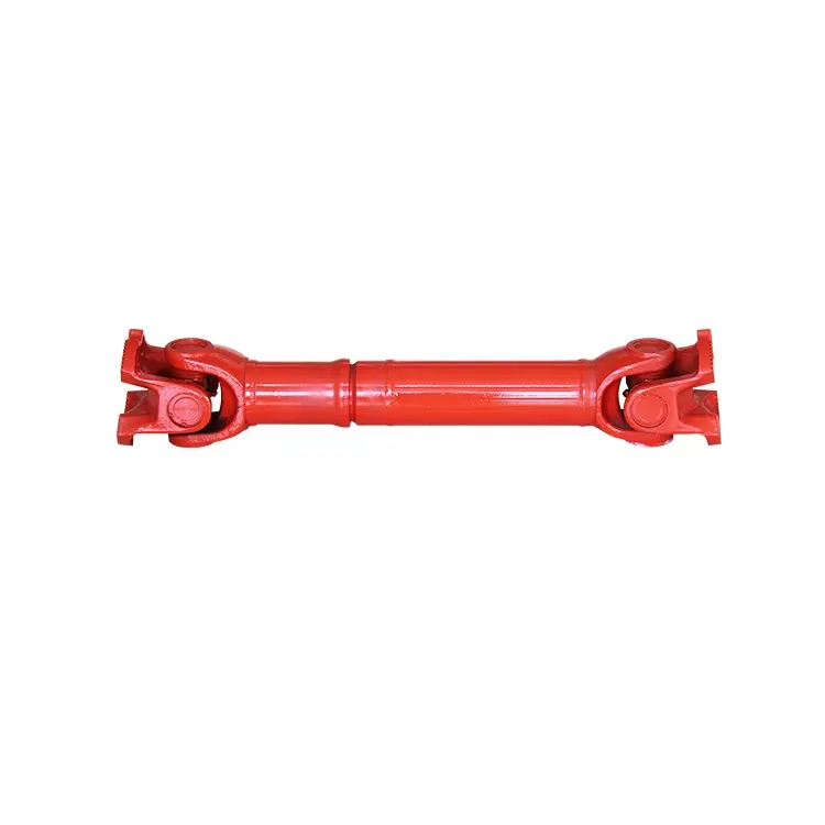
Drive shaft type
The driveshaft transfers torque from the engine to the wheels and is responsible for the smooth running of the vehicle. Its design had to compensate for differences in length and angle. It must also ensure perfect synchronization between its joints. The drive shaft should be made of high-grade materials to achieve the best balance of stiffness and elasticity. There are three main types of drive shafts. These include: end yokes, tube yokes and tapered shafts.
tube yoke
Tube yokes are shaft assemblies that use metallic materials as the main structural component. The yoke includes a uniform, substantially uniform wall thickness, a first end and an axially extending second end. The first diameter of the drive shaft is greater than the second diameter, and the yoke further includes a pair of opposing lugs extending from the second end. These lugs have holes at the ends for attaching the axle to the vehicle.
By retrofitting the driveshaft tube end into a tube fork with seat. This valve seat transmits torque to the driveshaft tube. The fillet weld 28 enhances the torque transfer capability of the tube yoke. The yoke is usually made of aluminum alloy or metal material. It is also used to connect the drive shaft to the yoke. Various designs are possible.
The QU40866 tube yoke is used with an external snap ring type universal joint. It has a cup diameter of 1-3/16″ and an overall width of 4½”. U-bolt kits are another option. It has threaded legs and locks to help secure the yoke to the drive shaft. Some performance cars and off-road vehicles use U-bolts. Yokes must be machined to accept U-bolts, and U-bolt kits are often the preferred accessory.
The end yoke is the mechanical part that connects the drive shaft to the stub shaft. These yokes are usually designed for specific drivetrain components and can be customized to your needs. Pat’s drivetrain offers OEM replacement and custom flanged yokes.
If your tractor uses PTO components, the cross and bearing kit is the perfect tool to make the connection. Additionally, cross and bearing kits help you match the correct yoke to the shaft. When choosing a yoke, be sure to measure the outside diameter of the U-joint cap and the inside diameter of the yoke ears. After taking the measurements, consult the cross and bearing identification drawings to make sure they match.
While tube yokes are usually easy to replace, the best results come from a qualified machine shop. Dedicated driveshaft specialists can assemble and balance finished driveshafts. If you are unsure of a particular aspect, please refer to the TM3000 Driveshaft and Cardan Joint Service Manual for more information. You can also consult an excerpt from the TSB3510 manual for information on angle, vibration and runout.
The sliding fork is another important part of the drive shaft. It can bend over rough terrain, allowing the U-joint to keep spinning in tougher conditions. If the slip yoke fails, you will not be able to drive and will clang. You need to replace it as soon as possible to avoid any dangerous driving conditions. So if you notice any dings, be sure to check the yoke.
If you detect any vibrations, the drivetrain may need adjustment. It’s a simple process. First, rotate the driveshaft until you find the correct alignment between the tube yoke and the sliding yoke of the rear differential. If there is no noticeable vibration, you can wait for a while to resolve the problem. Keep in mind that it may be convenient to postpone repairs temporarily, but it may cause bigger problems later.
end yoke
If your driveshaft requires a new end yoke, CZPT has several drivetrain options. Our automotive end yoke inventory includes keyed and non-keyed options. If you need tapered or straight holes, we can also make them for you.
A U-bolt is an industrial fastener that has U-shaped threads on its legs. They are often used to join two heads back to back. These are convenient options to help keep drivetrain components in place when driving over rough terrain, and are generally compatible with a variety of models. U-bolts require a specially machined yoke to accept them, so be sure to order the correct size.
The sliding fork helps transfer power from the transfer case to the driveshaft. They slide in and out of the transfer case, allowing the u-joint to rotate. Sliding yokes or “slips” can be purchased separately. Whether you need a new one or just a few components to upgrade your driveshaft, 4 CZPT Parts will have the parts you need to repair your vehicle.
The end yoke is a necessary part of the drive shaft. It connects the drive train and the mating flange. They are also used in auxiliary power equipment. CZPT’s drivetrains are stocked with a variety of flanged yokes for OEM applications and custom builds. You can also find flanged yokes for constant velocity joints in our extensive inventory. If you don’t want to modify your existing drivetrain, we can even make a custom yoke for you.
editor by CX 2023-05-10
China Best 90 Degree Hollow Shaft Gear Box, Right Angle Pump Drive Hollow Shaft Price drive shaft equipment
Merchandise Description
We are professional very best ninety degree hollow shaft gear box, appropriate angle pump generate hollow shaft producers and suppliers from China. All 90 diploma hollow shaft gear box, right angle pump drive hollow shaft will be tested and inspection reports just before items cargo.
JTP Series Cubic Bevel Gearbox
Jacton JTP series cubic bevel gearbox is also identified as cubic proper angle miter gearbox, cubic ninety diploma bevel gearbox, cubic miter bevel equipment box, or cubic spiral bevel equipment reducers. JTP sequence cubic bevel gearbox is a appropriate-angle shaft kind equipment box of spiral bevel gears for basic programs with high transmission capacity, large overall performance and higher effectiveness. 1:1, 1.5:1, 2:1, 3:1, 4:1 and 5:1 gear ratios as common. 2 way(1 enter 1 output), 3 way(1 enter 2 output, or 2 enter 1 output), 4 way(two enter 2 output) generate shafts as common. Reliable shaft as standard, customise hollow shaft or motor flange to bolt an IEC motor flange. Greatest torque 1299N.m. Maximum enter and output pace 1450RPM. There are 8 models: JTP65 mini cubic bevel gearbox, JTP90 cubic bevel gearbox, JTP110 cubic bevel gearbox, JTP140 cubic bevel gearbox, JTP170 cubic bevel gearbox, JTP210 cubic bevel gearbox, JTP240 cubic bevel gearbox and JTP280 cubic bevel gearbox.
| JTP65 Mini Cubic Bevel Gearbox one. bevel equipment ratio 1:one two. reliable travel shafts diameter12mm three. solid input and output shaft shafts 4. 2 way, 3 way, 4 way gearbox five. input electricity maximum 1.8Kw six. drive torque highest 13.5Nm 7. highest enter 156567X3, registered Money 500000CNY) is a leading manufacturer and provider in China for screw jacks (mechanical actuators), bevel gearboxes, lifting systems, linear actuators, gearmotors and pace reducers, and other folks linear motion and power transmission merchandise. We are Alibaba, Created-In-China and SGS (Serial NO.: QIP-ASI192186) audited manufacturer and provider. We also have a strict quality method, with senior engineers, skilled expert staff and practiced income teams, we constantly give the higher high quality equipments to meet up with the consumers electro-mechanical actuation, lifting and positioning requirements. CZPT Business guarantees good quality, reliability, functionality and price for today’s demanding industrial apps. Website 1: http://screw-jacks Site 2:
###
###
###
###
###
###
###
###
###
###
How to tell if your driveshaft needs replacingWhat is the cause of the unbalanced drive shaft? Unstable U-joint? Your car may make clicking noises while driving. If you can hear it from both sides, it might be time to hand it over to the mechanic. If you’re not sure, read on to learn more. Fortunately, there are many ways to tell if your driveshaft needs replacing. unbalancedAn unbalanced driveshaft can be the source of strange noises and vibrations in your vehicle. To fix this problem, you should contact a professional. You can try a number of things to fix it, including welding and adjusting the weight. The following are the most common methods. In addition to the methods above, you can use standardized weights to balance the driveshaft. These standardized weights are attached to the shaft by welders. unstableWhen the angular velocity of the output shaft is not constant, it is unstable. The angular velocity of the output shaft is 0.004 at ph = 29.5 and 1.9 at t = 1.9. The angular velocity of the intermediate shaft is not a problem. But when it’s unstable, the torque applied to it is too much for the machine. It might be a good idea to check the tension on the shaft. UnreliableIf you’re having trouble driving your car, chances are you’ve run into an unreliable driveshaft. This type of drivetrain can cause the wheels to stick or not turn at all, and also limit the overall control of the car. Whatever the reason, these issues should be resolved as soon as possible. Here are some symptoms to look for when diagnosing a driveshaft fault. Let’s take a closer look. Unreliable U-jointsA car with an unreliable U-joint on the drive shaft can be dangerous. A bad u-joint can prevent the vehicle from driving properly and may even cause you trouble. Unreliable u-joints are cheap to replace and you should try getting parts from quality manufacturers. Unreliable U-joints can cause the car to vibrate in the chassis or gear lever. This is a sure sign that your car has been neglected in maintenance. damaged drive shaftThe driveshaft is the part of the vehicle that connects the wheels. If the driveshaft is damaged, the wheels may stop turning and the vehicle may slow down or stop moving completely. It bears the weight of the car itself as well as the load on the road. So even a slight bend or break in the drive shaft can have dire consequences. Even a piece of loose metal can become a lethal missile if dropped from a vehicle. Maintenance feesThe cost of repairing a driveshaft varies widely, depending on the type and cause of the problem. A new driveshaft costs between $300 and $1,300, including labor. Repairing a damaged driveshaft can cost anywhere from $200 to $300, depending on the time required and the type of parts required. Symptoms of a damaged driveshaft include unresponsiveness, vibration, chassis noise and a stationary car.
China factory dc 12v double shaft electric dc worm gear box reduction motor with Best Sales dc 12v double shaft electric dc worm gear box reduction motor The clear view of Reversible dc 12v double shaft electric The specification of worm gear motor can be customized Reversible dc 12v double shaft electric dimension drawing FAQQ1 Access to motor product information. Company Information Contact us Worm Shafts and GearboxesIf you have a gearbox, you may be wondering what the best Worm Shaft is for your application. There are several things to consider, including the Concave shape, Number of threads, and Lubrication. This article will explain each factor and help you choose the right Worm Shaft for your gearbox. There are many options available on the market, so don’t hesitate to shop around. If you are new to the world of gearboxes, read on to learn more about this popular type of gearbox. Concave shapeThe geometry of a worm gear varies considerably depending on its manufacturer and its intended use. Early worms had a basic profile that resembled a screw thread and could be chased on a lathe. Later, tools with a straight sided g-angle were developed to produce threads that were parallel to the worm’s axis. Grinding was also developed to improve the finish of worm threads and minimize distortions that occur with hardening. Thread patternA good worm gear requires a perfect thread pattern. There are a few key parameters that determine how good a thread pattern is. Firstly, the threading pattern must be ACME-threaded. If this is not possible, the thread must be made with straight sides. Then, the linear pitch of the “worm” must be the same as the circular pitch of the corresponding worm wheel. In simple terms, this means the pitch of the “worm” is the same as the circular pitch of the worm wheel. A quick-change gearbox is usually used with this type of worm gear. Alternatively, lead-screw change gears are used instead of a quick-change gear box. The pitch of a worm gear equals the helix angle of a screw. Number of threadsDifferent types of worm gears use different numbers of threads on their planetary gears. A single threaded worm gear should not be used with a double-threaded worm. A single-threaded worm gear should be used with a single-threaded worm. Single-threaded worms are more effective for speed reduction than double-threaded ones. LubricationThe lubrication of a worm gear is particularly challenging, due to its friction and high sliding contact force. Fortunately, there are several options for lubricants, such as compounded oils. Compounded oils are mineral-based lubricants formulated with 10 percent or more fatty acid, rust and oxidation inhibitors, and other additives. This combination results in improved lubricity, reduced friction, and lower sliding wear.
in Manila Philippines sales price shop near me near me shop factory supplier Sinotruk HOWO Truck Spare Parts Fuel Injection Pump Gear Vg1560130064 manufacturer best Cost Custom Cheap wholesaler
Moreover, WE CAN Generate Custom-made VARIATORS, GEARED MOTORS, Electrical MOTORS AND OTHER HYDRAULIC Merchandise In accordance TO CUSTOMERS’ DRAWINGS. Owing to our broad item assortment and rich ordeals in this market, In the meantime, our merchandise are created in accordance to higher top quality standards, and complying with the intercontinental advanced standard standards.
EPTT profile
What can we supply?
one.EPTTtruk/EPT motor parts Crankshaft, connecting rod, cylinEPTTblock, cylinEPTThead, piston,flywheel, cylinEPTTliner,piston ,piston rings, piston pin,connecting rod,bearing, crankshaft bearing ,intake ampexhaust valve, valveEPTs,camshaft, tappets, camshafts bearing, fuel tank, fuel pump, gas filter,air filter, oil filter, battery,alternator, starter, starter motor, ignition coil,water pump, radiator, fan couplings, admirer, thermostat, oil pump,strain limiting valve .. 2.EPTTtruk/Quickly EPTT Elements EPTry shaft, 2nd shaft, intermediate shaft, two / 3 connected EPT,2nd velocity EPT(one/two/three/4/5) , reverse EPT ,intermediate shaft(one/two/3/four/5),synchronize assembly, synchronizer slider,EPTT ,EPTT shell, EPTT include, EPTT middle go over, change fork assembly, PTO… 3.Chassis parts/Cabin spare components EPTT cover, clutch disk , wheel hub, brake drum, brake pads ,Brake sneakers, lock, wiring harness, EPT shaft, front axle, steering knuckle,steering arm, EPT joints, rear axle , main EPTT,differential,axle, planetary EPTs, EPTTEPT, pinion and EPTTl EPT, EPT, EPT absorbers, stabilizer bars,steering pole, straigEPTT rod, rod joint, wheel EPTT, via axle, rear shell … .. WHY Choose US:
Certifications FAQ Q1. What is your terms of EPTT? Q2. What is your conditions of payment? Q3. What is your phrases of supply? This autumn. How about your delivery time? Q5. Can you generate according to the samples? Q6. Do you take a look at all your merchandise ahead of shipping? Q7: How do you make our organization EPTT-term and excellent partnership?
in Bunia Democratic Republic of the Congo sales price shop near me near me shop factory supplier Big Transmission Torque Gear Coupling with Elastic Pin manufacturer best Cost Custom Cheap wholesaler
Maintaining in thoughts that excellent services is the key to cooperating with clientele, we strive to meet substantial good quality requirements, offer you competitive rates and make certain prompt shipping. Our principal items are Needle Roller bearings, Cylindrical Roller Bearings, Rod stop Bearings, Spherical plain bearings, Keep track of roller Bearings for Guideway, Roller Bearings, Merge Bearings for forklifts, Drinking water Pump Bearings, SNR Vehicle Bearings and all sorts of Spherical Bearings. We examine every single piece of bearing by ourselves ahead of delivery. LZ Elastic Pin EPT Coupling(GB/T5015-2003) LZ EPT EPTT Elastic Pin EPT Coupling uses EPT rod to flip the column pin into the reverse hole among the two fifty percent coupling and the outer ring inner floor, and transfers the torque by means of the column pin to realize the relationship in between two fifty percent couplings. It has specified shaft offset payment potential and EPT absorption performance. LZ EPT EPTT Elastic Pin EPT Coupling is symmetrical and interchangeable, EPTT lifestyle, enabling large aXiHu (West EPT) Dis.al motion, and has the performance of cushioning, damping, dress in resistance and so on. The shaft holes of the two axle head of the pin sort coupling of the LZ elastic column are all straigEPTT holes. #9830LZ Elastic Pin EPT Coupling Simple Parameter And Principal Diamention(GB/T5015-2003)
#9830Product EPTT #9830Other EPT Listing
#9830Our EPTT Welcome to customize merchandise from our factory and please supply your style drawings or make contact with us if you require other demands. #9830Our Companies two.Product Solutions three.Samples Process 4.EPT amp DeveXiHu (West EPT) Dis.Hu (West EPT) Dis.ment 5.EPTT EPTT #9830FAQ Q two:Can you do OEM? Q 3:How EPTT is your shipping time? Q four: Do you offer samples ? Is it free or additional ? Q five: How EPTT is your guarantee? Q six: What is the MOQ? Q 7: Do you have inspection methods for coupling ? Q eight: Can I have a check out to your factory ahead of the purchase? Q 9: What is your payment? #9830Contact Us
in Kisangani Democratic Republic of the Congo sales price shop near me near me shop factory supplier High Pressure Hydraulic Power Unit Hydraulic Gear Pump Cbkg-G427-Afq11 manufacturer best Cost Custom Cheap wholesaler
Our products are used in many fields. ensures the security and consistency of the essential purpose of elements. We inspect each piece of bearing by ourselves just before delivery.
Functionality Characteristics:
| |||||||||||||||||||||||||||||||||||||||||||||||||||||||||||||||||||||||||||||||||||||||||||||||||||||||||||||||||||||||||||||||||||||||||||||||||||||||||||||||||||||||||||||||||||||||||||||||||||||||||||||||||||||||||||||||||||||||||||||||||||||||||||||||||||||||||||||||||||||||||||||||||||||||||||||||||||||||||||||||||||||||||||||||||||||||||||||||||||||||||||||||||||||||||||||||||||||||||||||||||||||||||||||||||||||||||||||


